Installation
INSTALLATION
PROCEDURE
1. INSTALL NO. 1 SWITCH WIRE
HINT:
Perform this procedure only when replacement of the No. 1 switch wire is necessary.
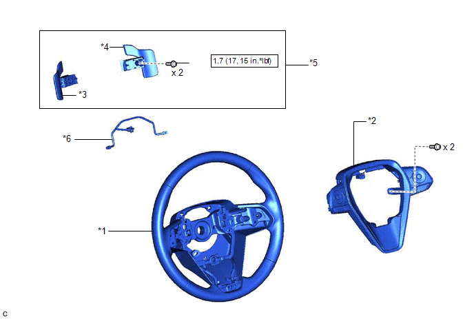
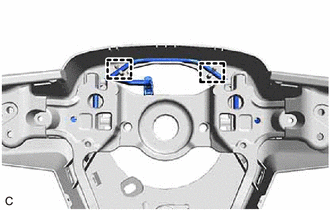
(a) Engage the 2 guides to install the No. 1 switch wire to the steering wheel assembly.
2. INSTALL SHIFT PADDLE SWITCH (TRANSMISSION SHIFT SWITCH ASSEMBLY)
(a)
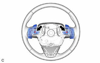
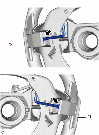
Connect the No. 1 transmission shift switch assembly connector and No. 2
transmission shift switch assembly connector to install the No. 1
transmission shift switch assembly and No. 2 transmission shift switch
assembly to the No. 1 switch wire.
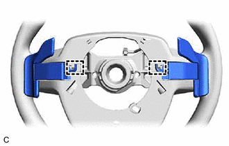
(b) Engage the 2 clamps.
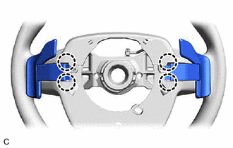
(c) Engage the 4 claws to install the shift paddle switch (transmission shift switch assembly) to the steering wheel assembly.
(d) Install 2 new screws.
Torque:
1.7 N┬Ęm {17 kgf┬Ęcm, 15 in┬Ęlbf}
3. INSTALL STEERING PAD SWITCH ASSEMBLY
Click here

4. INSTALL STEERING WHEEL ASSEMBLY
Click here 
Removal
REMOVAL
CAUTION / NOTICE / HINT
The
necessary procedures (adjustment, calibration, initialization, or
registration) that must be performed after parts are removed and
installed, or replaced during shift paddle switch (transmission shift
switch assembly) removal/installation are shown below.
Necessary Procedures After Parts Removed/Installed/Replaced |
Replaced Part or Performed Procedure |
Necessary Procedure | Effect/Inoperative Function when Necessary Procedure not Performed |
Link |
|
*: When performing learning using the Techstream.
Click here  |
|
Auxiliary battery terminal is disconnected/reconnected |
Perform steering sensor zero point calibration |
Lane departure alert system (w/ Steering Control) |
 |
|
Pre-collision system |
|
Intelligent clearance sonar system* |
|
Lighting system (w/ AFS)(EXT) |
|
Memorize steering angle neutral point |
Parking assist monitor system |
 |
|
Panoramic view monitor system |
 |
NOTICE:
- Do not remove/install the spiral cable with sensor sub-assembly with the battery connected and the power switch on (IG).
- Do not rotate the spiral cable with sensor sub-assembly without the
steering wheel assembly installed, with the battery connected and the
power switch on (IG).
- Ensure that the steering wheel assembly is installed and aligned straight when inspecting the steering sensor.
PROCEDURE
1. REMOVE STEERING WHEEL ASSEMBLY
Click here 
2. REMOVE STEERING PAD SWITCH ASSEMBLY
Click here 
3. REMOVE SHIFT PADDLE SWITCH (TRANSMISSION SHIFT SWITCH ASSEMBLY)
| (b) Disengage the 4 claws. | |
| (c)
Disengage the 2 clamps to disconnect the shift paddle switch
(transmission shift switch assemby) from the steering wheel assembly. |
|
| (d)
Disconnect the No. 1 transmission shift switch assembly connector and
No. 2 transmission shift switch assembly connector to remove the No. 1
transmission shift switch assembly and No. 2 transmission shift switch
assembly from the No. 1 switch wire. |
 |
|
*1 | No.1 Transmission Shift Switch Assembly | |
*2 | No.2 Transmission Shift Switch Assembly | | |
4. REMOVE NO. 1 SWITCH WIRE
HINT:
Perform this procedure only when replacement of the No. 1 switch wire is necessary.
| (a) Disengage the 2 guides and remove the No. 1 switch wire from the steering wheel assembly. |
|
