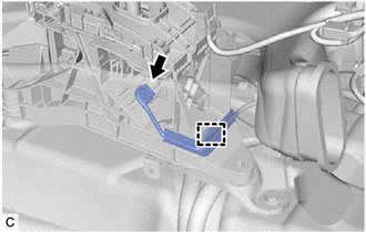
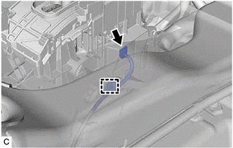
Components
COMPONENTS
ILLUSTRATION
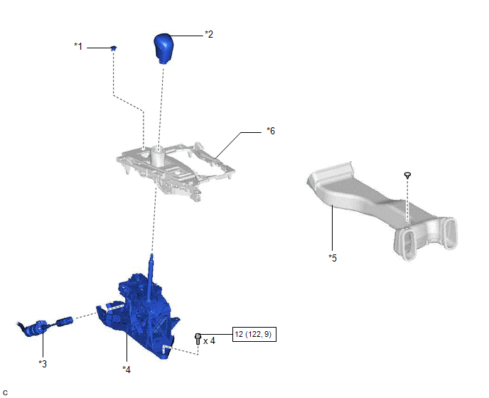
|
*1 | SHIFT LOCK RELEASE BUTTON COVER |
*2 | SHIFT LEVER KNOB SUB-ASSEMBLY |
|
*3 | TRANSMISSION CONTROL CABLE ASSEMBLY |
*4 | TRANSMISSION FLOOR SHIFT ASSEMBLY |
|
*5 | NO. 1 CONSOLE BOX DUCT |
*6 | REAR UPPER CONSOLE PANEL SUB-ASSEMBLY |
 |
N*m (kgf*cm, ft.*lbf): Specified torque |
- | - |
ILLUSTRATION
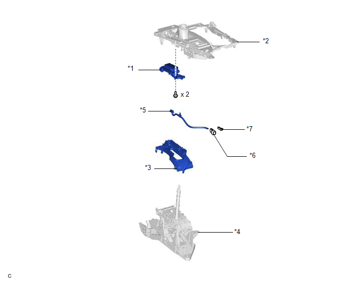
|
*1 | SHIFT POSITION INDICATOR |
*2 | REAR UPPER CONSOLE PANEL SUB-ASSEMBLY |
|
*3 | LOWER POSITION INDICATOR HOUSING |
*4 | SHIFT LOCK CONTROL UNIT ASSEMBLY |
|
*5 | INDICATOR LIGHT WIRE SUB-ASSEMBLY |
*6 | CONNECTOR HOUSING |
|
*7 | CLAMP |
- | - |
Disassembly
DISASSEMBLY
PROCEDURE
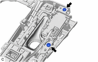
1. REMOVE SHIFT POSITION INDICATOR
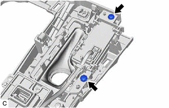
| (a) Disengage the 2 clamps to disconnect the wire harness. |
|
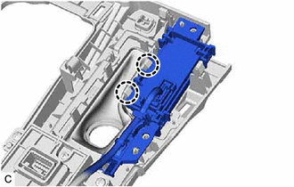
| (c) Disengage the 2 claws and remove the shift position indicator from the rear upper console panel sub-assembly. |
|
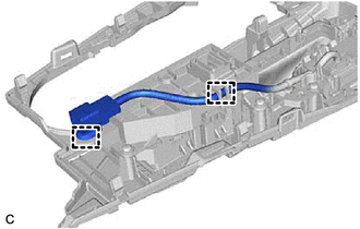
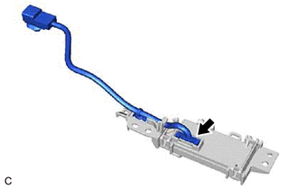
2. REMOVE INDICATOR LIGHT WIRE SUB-ASSEMBLY
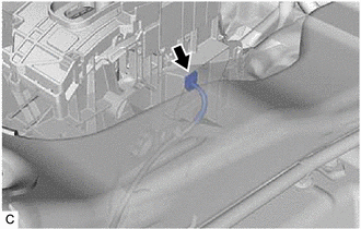
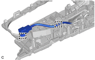
| (a) Disconnect the indicator light wire sub-assembly connector. |
|
| (b) Disengage the clamp and guide to remove the indicator light wire sub-assembly from the shift position indicator. |
|
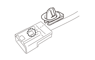
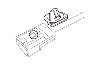
| (c) Disengage the claw to remove the clamp from the indicator light wire sub-assembly. |
|
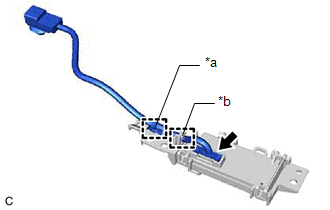
| (d) Using a screwdriver with its tip wrapped with protective tape, release the secondary lock. |
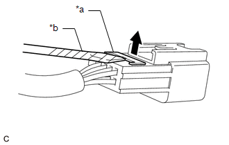 |
|
*a | Secondary Lock | |
*b | Protective Tape | | |
(e) Using SST, release the locking lug of each terminal and remove the terminal from the connector housing.
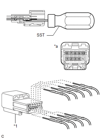
|
*1 | Connector Housing |
|
*a | Rear view of wire harness connector |
 |
Shift Position Indicator Terminal |
SST: 09991-00510
NOTICE:
Before removing the terminals, make a note of the color of each wire and position where its terminal is installed.
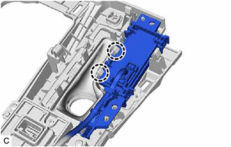
3. REMOVE LOWER POSITION INDICATOR HOUSING
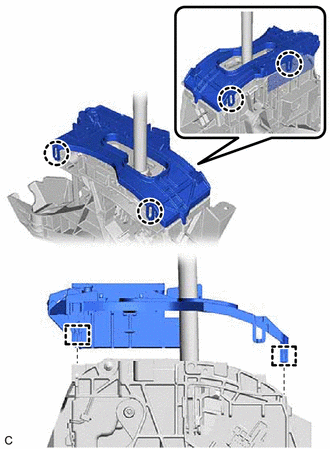
| (a) Disengage the 4 claws and 2 guides to remove the lower position indicator housing from the shift lock control unit assembly.
NOTICE: Do not damage the lower position indicator housing. |
|
Inspection
INSPECTION
PROCEDURE
1. INSPECT SHIFT LOCK CONTROL ECU
HINT:
If
the results of the following inspections are as specified but a
malfunction has occurred, replace the shift lock control unit assembly.
(a) Inspect wire harness:
| (1) Disconnect the shift lock control ECU connector. | |
| (2) Measure the voltage according to the value(s) in the table below.
Standard Voltage: |
Tester Connection | Condition |
Specified Condition | |
5 (IG) - Body ground |
Power switch on (IG) |
11 to 14 V | |
Power switch off |
Below 1 V | If the result is not as specified, repair or replace the shift lock control ECU wire harness. |
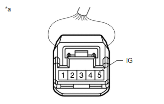 |
|
*a | Front view of wire harness connector
(to Shift Lock Control ECU) | | |
| (3) Measure the voltage according to the value(s) in the table below.
Standard Voltage: |
Tester Connection | Condition |
Specified Condition | |
4 (STP) - Body ground |
Power switch on (IG), brake pedal depressed |
11 to 14 V | |
Power switch on (IG), brake pedal released |
Below 1 V | If
the result is not as specified, repair or replace the wire harness or
connector or replace the hybrid vehicle control ECU assembly. |
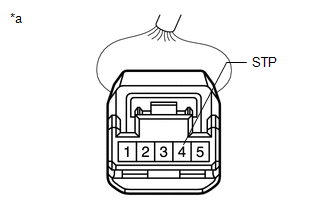 |
|
*a | Front view of wire harness connector
(to Shift Lock Control ECU) | | |
| (4) Measure the resistance according to the value(s) in the table below.
Standard Resistance: |
Tester Connection | Condition |
Specified Condition | |
1 (E) - Body ground |
Always | Below 1 Ω |
If the result is not as specified, repair or replace the shift lock control ECU wire harness. |
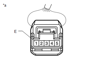 |
|
*a | Front view of wire harness connector
(to Shift Lock Control ECU) | | |
(b) Inspect shift lock solenoid:
| (1) Disconnect the shift lock solenoid connector. | |
| (2) Measure the resistance according to the value(s) in the table below.
Standard Resistance: |
Tester Connection | Condition |
Specified Condition | |
4 (P) - 3 (E2) | Shift lever in P |
10 kΩ or higher | |
Shift lever not in P |
Below 1 Ω | If the result is not as specified, replace the shift lock control unit assembly. |
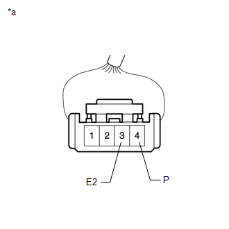 |
|
*a | Front view of wire harness connector
(to Shift Lock Solenoid) | | |
| (3) Measure the resistance according to the value(s) in the table below.
Standard Resistance: |
Tester Connection | Condition |
Specified Condition | |
1 (SLS+) - 2 (SLS-) |
Always | 112 Ω |
If the result is not as specified, replace the shift lock control unit assembly. |
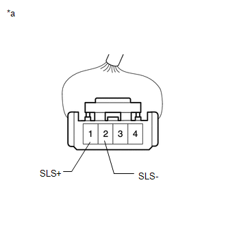 |
|
*a | Front view of wire harness connector
(to Shift Lock Solenoid) | | |
2. INSPECT TRANSMISSION CONTROL SWITCH
| (a) Disconnect the transmission control switch connector. |
|
| (b) Measure the resistance according to the value(s) in the table below.
Standard Resistance: |
Tester Connection | Condition |
Specified Condition | |
4 (IG) - 5 (S) | Shift lever in S, "+" or "-" |
Below 1 Ω | |
Shift lever not in S, "+" or "-" |
10 kΩ or higher | |
3 (SFTU) - 2 (E) |
Shift lever held in "+" (Up-shift) |
Below 1 Ω | |
Shift lever not held in "+" (Up-shift) |
10 kΩ or higher | |
1 (SFTD) - 2 (E) |
Shift lever held in "-" (Down-shift) |
Below 1 Ω | |
Shift lever not held in "-" (Down-shift) |
10 kΩ or higher | If the result is not as specified, replace the shift lock control unit assembly. |
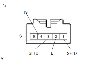 |
|
*a | Component without harness connected
(Transmission Control Switch (Transmission Floor Shift Assembly)) | | |
Installation
INSTALLATION
PROCEDURE
1. INSTALL TRANSMISSION FLOOR SHIFT ASSEMBLY
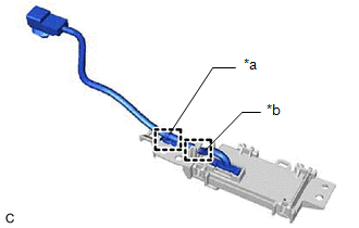
(a) Engage the clamp to connect the wire harness to the transmission floor shift assembly.
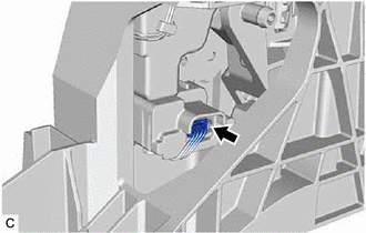
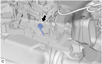
(b) Connect the shift lock control ECU connector.
(c) Engage the clamp to connect the wire harness to the transmission floor shift assembly.
(d) Connect the transmission control switch connector.
(e) Install the clip to the No. 1 console box duct.
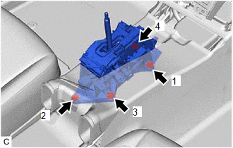
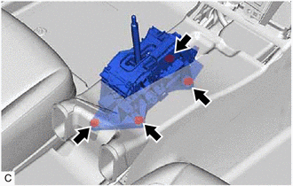
| (f) Temporarily install the transmission floor shift assembly to the vehicle body with the 4 bolts. |
|
(g) Tighten the 4 bolts in the order shown in the illustration.
Torque:
12 N·m {122 kgf·cm, 9 ft·lbf}
2. CONNECT TRANSMISSION CONTROL CABLE ASSEMBLY
NOTICE:
Before connecting the transmission control cable assembly, check that the shift lever is in N.
| (a)
Slide the slider of the transmission control cable assembly in the
direction indicated by the arrow in the illustration and pull the lock
piece outward. |
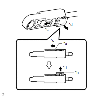 |
|
*a | Slider | |
*b | Lock Piece | |
*c | Slide | |
*d | Pull | | |
| (b)
Turn the lock nut of the transmission control cable assembly
counterclockwise. While holding the lock nut, push in the stopper. |
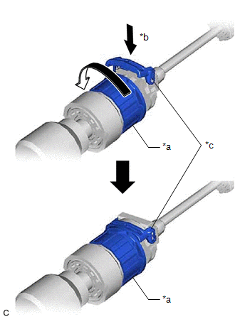 |
|
*a | Lock Nut | |
*b | Push in | |
*c | Stopper | | |
| (c) Connect the transmission control cable assembly to the transmission floor shift assembly.
NOTICE: After installation, check that the outer part of the stopper is as shown in the illustration. |
|
| (d) Connect the transmission control cable assembly to the transmission floor shift assembly.
NOTICE:
- Check that the lock piece is pulled out.
- Push the end of the transmission control cable assembly all the way to the base of the transmission floor shift assembly pin.
- Connect the transmission control cable assembly so that the lock piece faces the driver side.
|
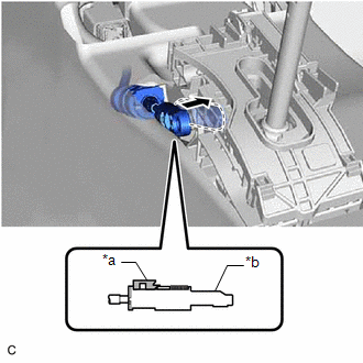 |
|
*a | Lock Piece | |
*b | Adjuster Case | | |
| (e) Push the lock piece into the adjuster case.
NOTICE:
- Check that the shift lever is in N.
- Securely push in the lock piece until the slider lock is engaged.
|
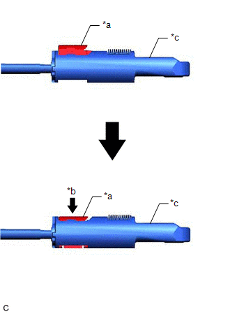 |
|
*a | Lock Piece | |
*b | Push in | |
*c | Adjuster Case | | |
(f)
After adjusting the shift lever position, check the position and
operation of the shift lever. If there is a problem, adjust the shift
lever position again.
3. INSTALL CONSOLE BOX ASSEMBLY
Click here

4. INSTALL SHIFT LEVER KNOB SUB-ASSEMBLY
Click here 
5. INSTALL SHIFT LOCK RELEASE BUTTON COVER
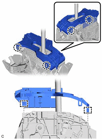
(a) Engage the 2 claws and guide to install the shift lock release button cover to the rear upper console panel sub-assembly.
6. INSPECT SHIFT LEVER POSITION
Click here

7. ADJUST SHIFT LEVER POSITION
Click here

On-vehicle Inspection
ON-VEHICLE INSPECTION
PROCEDURE
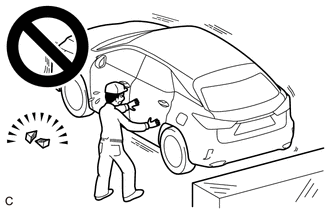
1. SECURE VEHICLE
(a) Fully apply the parking brake and chock a wheel.
CAUTION:
- Make sure to apply the parking brake and chock a wheel before performing this procedure.
- If the vehicle is not secure and the shift lever is moved to N, the
vehicle may suddenly move, possibly resulting in an accident or serious
injury.
2. INSPECT SHIFT LEVER POSITION
(a)
When moving the shift lever from P to R with the power switch on (IG)
and the brake pedal depressed, check that the shift lever moves smoothly
and correctly into position.
(b) Start the engine and
check that the vehicle moves forward when the shift lever is moved from
N to D and moves rearward when the shift lever is moved to R.
If the operation is not as specified, inspect or adjust the shift lever position sensor or transmission control cable assembly.
3. INSPECT SHIFT LOCK OPERATION
(a) Move the shift lever to P.
(b) Turn the power switch off.
(c) Check that the shift lever cannot be moved from P to any other position.
(d)
Turn the power switch on (IG), depress the brake pedal, and check that
the shift lever can be moved from P to any other position.
If the operation is not as specified, inspect the transmission floor shift assembly.
Click here 
4. INSPECT SHIFT LOCK RELEASE BUTTON OPERATION
(a) Move the shift lever to P.
(b) Turn the power switch off.
(c) Remove the shift lock release button cover.
Click here 
(d)
When moving the shift lever with the shift lock release button pressed,
check that the shift lever can be moved from P to any other position.
Reassembly
REASSEMBLY
PROCEDURE
1. INSTALL LOWER POSITION INDICATOR HOUSING
| (a) Engage the 4 claws and 2 guides to install the lower position indicator housing to the shift lock control unit assembly.
NOTICE: Do not damage the lower position indicator housing. |
|
2. INSTALL INDICATOR LIGHT WIRE SUB-ASSEMBLY
(a) Install each terminal to the connector housing as shown in the illustration.
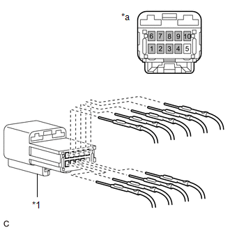
|
*1 | Connector Housing |
|
*a | Rear vew of wire harness connector |
 |
Shift Position Indicator Terminal |
| (b) Lock the secondary lock. | |
| (c) Engage the claw to install the clamp to the indicator light wire sub-assembly. |
|
| (d) Connect the indicator light wire sub-assembly connector. |
|
(e) Engage the clamp and guide to install the indicator light wire sub-assembly to the shift position indicator.
3. INSTALL SHIFT POSITION INDICATOR
| (a) Engage the 2 claws to install the shift position indicator to the rear upper console panel sub-assembly. |
|
| (b) Install the 2 screws. | |
| (c) Engage the 2 clamps to connect the wire harness. | |
Removal
REMOVAL
PROCEDURE
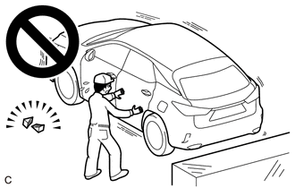
1. SECURE VEHICLE
(a) Fully apply the parking brake and chock a wheel.
CAUTION:
- Make sure to apply the parking brake and chock a wheel before performing this procedure.
- If the vehicle is not secure and the shift lever is moved to N, the
vehicle may suddenly move, possibly resulting in an accident or serious
injury.
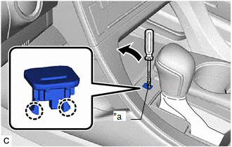
2. REMOVE SHIFT LOCK RELEASE BUTTON COVER
| (a)
Using a screwdriver with its tip wrapped with protective tape,
disengage the 2 claws to remove the shift lock release button cover from
the rear upper console panel sub-assembly. NOTICE: Be careful not to damage the shift lock release button cover and rear upper console panel sub-assembly. |
|
3. REMOVE SHIFT LEVER KNOB SUB-ASSEMBLY
Click here

4. REMOVE CONSOLE BOX ASSEMBLY
Click here

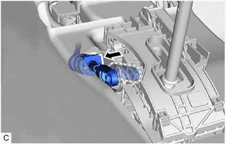
5. DISCONNECT TRANSMISSION CONTROL CABLE ASSEMBLY
(a) Move the shift lever to N.
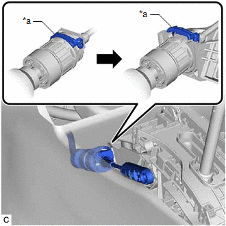
| (b) Disconnect the transmission control cable assembly from the transmission floor shift assembly. |
|
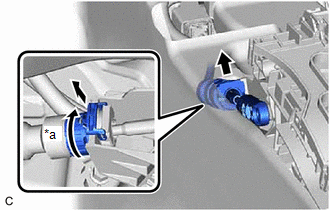
| (c)
Rotate the lock nut counterclockwise approximately 180° and, while
holding the lock nut in that position, disconnect the transmission
control cable assembly from the transmission floor shift assembly. |
|
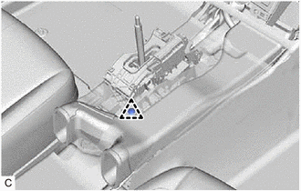
6. REMOVE TRANSMISSION FLOOR SHIFT ASSEMBLY
| (b) Remove the clip to disconnect the No. 1 console box duct from the transmission floor shift assembly. |
|
| (c) Disconnect the transmission control switch connector. |
|
(d) Disengage the clamp to disconnect the wire harness from the transmission floor shift assembly.
| (e) Disconnect the shift lock control ECU connector. | |
(f) Disengage the clamp to disconnect the wire harness from the transmission floor shift assembly.
(g) Remove the transmission floor shift assembly.


