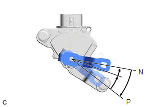
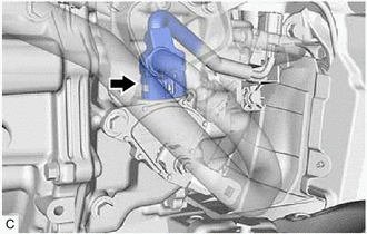
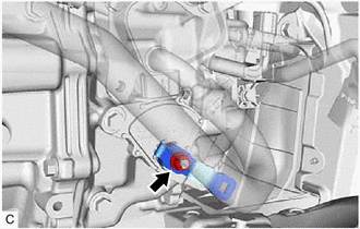
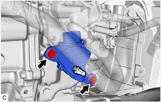
Adjustment
ADJUSTMENT
PROCEDURE
1. SECURE VEHICLE
(a) Fully apply the parking brake and chock a wheel.
CAUTION:
- Make sure to apply the parking brake and chock a wheel before performing this procedure.
- If the vehicle is not secure and the shift lever is moved to N, the
vehicle may suddenly move, possibly resulting in an accident or serious
injury.
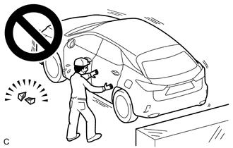
2. INSPECT SHIFT LEVER POSITION SENSOR POSITION
(a) Turn the power switch on (READY).
(b) Move the shift lever to D and release the brake pedal.
CAUTION:
Be sure to apply the parking brake and chock all 4 wheels to secure the vehicle.
| (c)
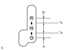
Slowly move the shift lever to N and measure the moving distance (A) of
the shift lever from the original point to the gear disengagement
point. NOTICE: Be sure to move the shift lever slowly. |
 |
|
*a | Gear Disengagement Point | | |
(d) Move the shift lever to R and release the brake.
CAUTION:
Be sure to apply the parking brake and chock all 4 wheels to secure the vehicle.
(e)
Slowly move the shift lever to N and measure the moving distance (B) of
the shift lever from the original point to the gear disengagement
point.
NOTICE:
Be sure to move the shift lever slowly.
(f) Check that the moving distances (A) and (B) shown in the illustration are almost the same.
HINT:
- If the moving distances (A) and (B) are almost the same, adjustment of the shift lever position is not necessary.
- If the moving distance (A) is shorter than (B), perform step [#1] of Adjust Shift Lever Position Sensor Position.
- If the moving distance (B) is shorter than (A), perform step [#2] of Adjust Shift Lever Position Sensor Position.
3. ADJUST SHIFT LEVER POSITION SENSOR POSITION
(a) If the moving distance (A) is shorter than (B). [#1]
HINT:
If
the shift lever is moved from R to N, the moving distance of the shift
lever from the original point to the gear disengagement point becomes
longer.
(1) Move the shift lever to N.
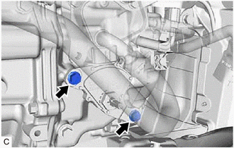
| (2) Loosen the 2 bolts.
NOTICE:
- Do not loosen the bolts by more than 2 rotations, or by more than 2.0 mm (0.0787 in.).
- If the bolts are loosened more than 2 rotations or 2.0 mm (0.0787 in.), replace them with new one.
| |
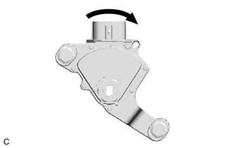
| (3) Slightly turn the shift lever position sensor clockwise. |
|
| (4) Tighten the 2 bolts. Torque: 11 N·m {112 kgf·cm, 8 ft·lbf} |
|
(5) Check the shift lever position sensor position.
(b) If the moving distance (B) is shorter than (A). [#2]
HINT:
If
the shift lever is moved from D to N, the moving distance of the shift
lever from the original point to the gear disengagement point becomes
longer.
(1) Move the shift lever to N.
| (2) Loosen the 2 bolts.
NOTICE:
- Do not loosen the bolts by more than 2 rotations, or by more than 2.0 mm (0.0787 in.).
- If the bolts are loosened more than 2 rotations or 2.0 mm (0.0787 in.), replace them with new one.
| |
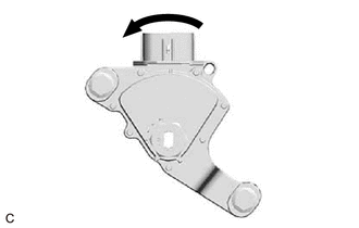
| (3) Slightly turn the shift lever position sensor counterclockwise. |
|
| (4) Tighten the 2 bolts. Torque: 11 N·m {112 kgf·cm, 8 ft·lbf} |
|
(5) Check the shift lever position sensor position.
Components
COMPONENTS
ILLUSTRATION
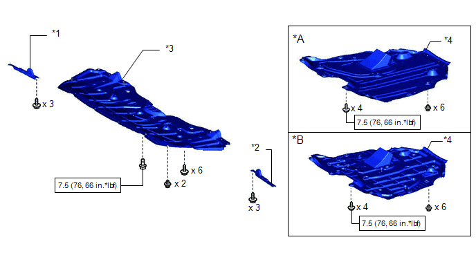
|
*A | Type A |
*B | Type B |
|
*1 | FRONT WHEEL OPENING EXTENSION PAD RH |
*2 | FRONT WHEEL OPENING EXTENSION PAD LH |
|
*3 | NO. 1 ENGINE UNDER COVER |
*4 | NO. 2 ENGINE UNDER COVER ASSEMBLY |
 |
N*m (kgf*cm, ft.*lbf): Specified torque |
- | - |
ILLUSTRATION
|
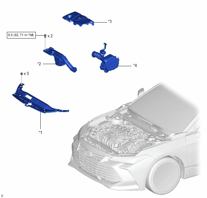
*1 | COOL AIR INTAKE DUCT SEAL |
*2 | INLET AIR CLEANER ASSEMBLY |
|
*3 | NO. 1 ENGINE COVER SUB-ASSEMBLY |
*4 | AIR CLEANER ASSEMBLY WITH AIR CLEANER HOSE |
 |
N*m (kgf*cm, ft.*lbf): Specified torque |
- | - |
ILLUSTRATION
|
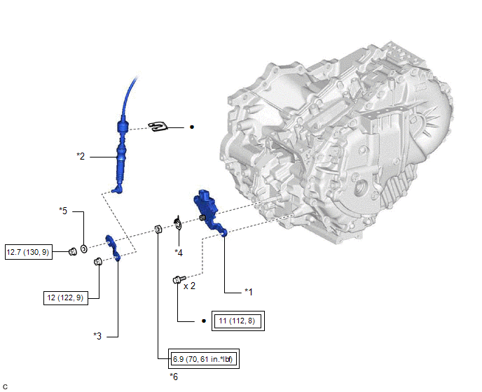
*1 | SHIFT LEVER POSITION SENSOR |
*2 | TRANSMISSION CONTROL CABLE ASSEMBLY |
|
*3 | CONTROL SHAFT LEVER |
*4 | LOCK PLATE |
|
*5 | WASHER |
*6 | LOCK NUT |
 |
Tightening torque for "Major areas involving basic vehicle performance such as moving/turning/stopping": N*m (kgf*cm, ft.*lbf) |
 |
N*m (kgf*cm, ft.*lbf): Specified torque |
|
â—Ź | Non-reusable part |
- | - |
Inspection
INSPECTION
PROCEDURE
1. INSPECT SHIFT LEVER POSITION SENSOR
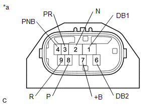
| (a) Measure the resistance according to the value(s) in the table below.
Standard Resistance: |
Tester Connection | Condition |
Specified Condition | |
7 (+B) - 3 (PR) |
Shift lever in P |
Below 1 Ω | |
7 (+B) - 4 (PNB) |
Below 1 Ω | |
7 (+B) - 8 (P) | Below 1 Ω | |
7 (+B) - 1 (DB1), 2 (N), 6 (DB2) or 9 (R) |
Shift lever in P |
10 kΩ or higher | |
7 (+B) - 3 (PR) |
Shift lever in R |
Below 1 Ω | |
7 (+B) - 9 (R) | Below 1 Ω | |
7 (+B) - 1 (DB1), 2 (N), 4 (PNB), 6 (DB2) or 8 (P) |
Shift lever in R |
10 kΩ or higher | |
7 (+B) - 2 (N) |
Shift lever in N |
Below 1 Ω | |
7 (+B) - 4 (PNB) |
Below 1 Ω | |
7 (+B) - 1 (DB1), 3 (PR), 6 (DB2), 8 (P) or 9 (R) |
Shift lever in N |
10 kΩ or higher | |
7 (+B) - 1 (DB1) |
Shift lever in D or S |
Below 1 Ω | |
7 (+B) - 6 (DB2) |
Below 1 Ω | |
7 (+B) - 2 (N), 3 (PR), 4 (PNB), 8 (P) or 9 (R) |
Shift lever in D or S |
10 kΩ or higher | HINT: The shift lever position sensor connector (shift lever position sensor side) does not have a terminal 5.
If the result is not as specified, replace the shift lever position sensor. |
 |
|
*a | Component without harness connected
(Shift Lever Position Sensor) | | |
Installation
INSTALLATION
PROCEDURE
1. INSTALL SHIFT LEVER POSITION SENSOR
(a) Move the shift lever to N.
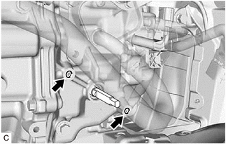
| (b) Clean and degrease the 2 bolt holes of the hybrid vehicle transaxle assembly. |
|
(c) Temporarily install the shift lever position sensor to the hybrid vehicle transaxle assembly with 2 new bolts.
NOTICE:
- Do not reuse the shift lever position sensor if it has been dropped or subjected to a severe impact.
- Do not allow moisture to adhere to the connector terminal.
(d) Install the lock plate to the shift lever position sensor with the lock nut.
Torque:
6.9 N·m {70 kgf·cm, 61 in·lbf}
(e) Temporarily install the control shaft lever to the shift lever position sensor.
| (f) Turn the control shaft lever clockwise until it stops, then turn it counterclockwise 2 notches. |
|
(g) Remove the control shaft lever from the shift lever position sensor.
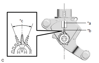
| (h) Align the indicator with the neutral basic line. NOTICE:
The
indicator of the lock plate has a certain amount of play. Align the
center point of the range of play with the neutral basic line. |
 |
|
*a | Neutral Basic Line | |
*b | Indicator | |
*c | Range of Play | | |
(i) Tighten the 2 bolts.
Torque:
11 N·m {112 kgf·cm, 8 ft·lbf}
(j) Using a screwdriver with its tip wrapped with protective tape, secure the lock nut with the lock plate.
(k) Install the control shaft lever and washer to the shift lever position sensor with the nut.
Torque:
12.7 N·m {130 kgf·cm, 9 ft·lbf}
(l) Connect the shift lever position sensor connector.
2. CONNECT TRANSMISSION CONTROL CABLE ASSEMBLY
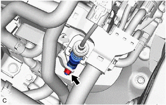
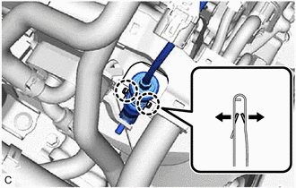
(a) Engage the 2 claws to install a new clip to the transmission control cable assembly.
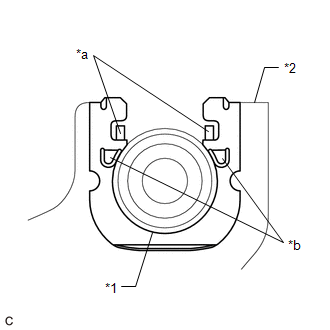
| (b)
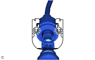
Using a screwdriver, engage the 4 claws and install the transmission
control cable assembly to the No. 1 transmission control cable bracket.
NOTICE:
- Make sure that the claws (A) of the clip are securely engaged in the grooves of the bracket.
- Make sure that the transmission control cable assembly is securely installed inside of the claws (B) of the clip.
|
 |
|
*1 | Transmission Control Cable Assembly | |
*2 | No. 1 Transmission Control Cable Bracket | |
*a | Claw (A) | |
*b | Claw (B) | | |
(c) Connect the transmission control cable assembly to the control shaft lever with the nut.
Torque:
12 N·m {122 kgf·cm, 9 ft·lbf}
3. INSTALL AIR CLEANER ASSEMBLY WITH AIR CLEANER HOSE
Click here 
4. INSTALL NO. 1 ENGINE COVER SUB-ASSEMBLY
Click here 
5. INSTALL INLET AIR CLEANER ASSEMBLY
Click here 
6. INSTALL COOL AIR INTAKE DUCT SEAL
Click here 
7. INSPECT SHIFT LEVER POSITION SENSOR POSITION
Click here 
8. ADJUST SHIFT LEVER POSITION SENSOR POSITION
Click here 
9. INSPECT SHIFT LEVER POSITION
Click here 
10. ADJUST SHIFT LEVER POSITION
Click here 
11. INSTALL NO. 2 ENGINE UNDER COVER ASSEMBLY
Click here 
12. INSTALL NO. 1 ENGINE UNDER COVER
Click here 
13. INSTALL FRONT WHEEL OPENING EXTENSION PAD LH
Click here 
14. INSTALL FRONT WHEEL OPENING EXTENSION PAD RH
Click here 
Removal
REMOVAL
PROCEDURE
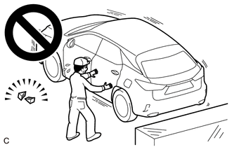
1. SECURE VEHICLE
(a) Fully apply the parking brake and chock a wheel.
CAUTION:
- Make sure to apply the parking brake and chock a wheel before performing this procedure.
- If the vehicle is not secure and the shift lever is moved to N, the
vehicle may suddenly move, possibly resulting in an accident or serious
injury.
2. REMOVE FRONT WHEEL OPENING EXTENSION PAD RH
Click here 
3. REMOVE FRONT WHEEL OPENING EXTENSION PAD LH
Click here 
4. REMOVE NO. 1 ENGINE UNDER COVER
Click here 
5. REMOVE NO. 2 ENGINE UNDER COVER ASSEMBLY
Click here 
6. REMOVE COOL AIR INTAKE DUCT SEAL
Click here 
7. REMOVE INLET AIR CLEANER ASSEMBLY
Click here 
8. REMOVE NO. 1 ENGINE COVER SUB-ASSEMBLY
Click here 
9. REMOVE AIR CLEANER ASSEMBLY WITH AIR CLEANER HOSE
Click here 
10. DISCONNECT TRANSMISSION CONTROL CABLE ASSEMBLY
(a) Move the shift lever to N.
| (b) Remove the nut and disconnect the transmission control cable assembly from the control shaft lever. |
|
| (c)
Using a screwdriver, disengage the 4 claws and disconnect the
transmission control cable assembly with the clip from the No. 1
transmission control cable bracket. | |
| (d) Using a screwdriver, disengage the 2 claws and remove the clip from the transmission control cable assembly. |
|
11. REMOVE SHIFT LEVER POSITION SENSOR
| (a) Disconnect the shift lever position sensor connector. |
|
| (b) Remove the nut, washer and control shaft lever from the shift lever position sensor. |
|
| (c) Using a screwdriver with its tip wrapped with protective tape, pry out the tabs of the lock plate. |
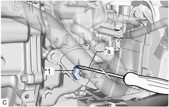 |
|
*1 | Lock Plate | |
*a | Protective Tape | | |
| (d) Remove the lock nut and lock plate from the shift lever position sensor. |
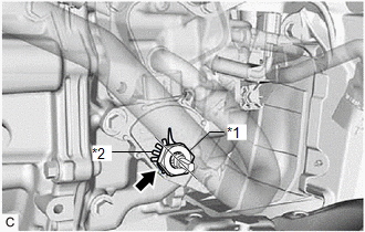 |
|
*1 | Lock Nut | |
*2 | Lock Plate | | |
| (e) Remove the 2 bolts and shift lever position sensor from the hybrid vehicle transaxle assembly. |
|


