Components
COMPONENTS
ILLUSTRATION
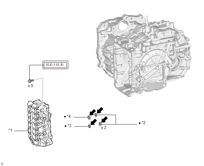
|
*1 | TRANSMISSION VALVE BODY ASSEMBLY |
*2 | TRANSAXLE CASE GASKET |
|
*3 | NO. 1 FRONT OIL PUMP COVER GASKET |
*4 | NO. 2 FRONT OIL PUMP COVER GASKET |
 |
Tightening torque for "Major areas involving basic vehicle performance such as moving/turning/stopping": N*m (kgf*cm, ft.*lbf) |
â—Ź | Non-reusable part |
 |
Toyota Genuine ATF WS |
- | - |
ILLUSTRATION
|
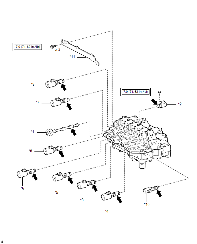
*1 | MANUAL VALVE |
*2 | SOLENOID (SL) VALVE |
|
*3 | SOLENOID (SL1) VALVE |
*4 | SOLENOID (SL2) VALVE |
|
*5 | SOLENOID (SL3) VALVE |
*6 | SOLENOID (SL4) VALVE |
|
*7 | SOLENOID (SL5) VALVE |
*8 | SOLENOID (SL6) VALVE |
|
*9 | SOLENOID (SLU) VALVE |
*10 | SOLENOID (SLT) VALVE |
|
*11 | SOLENOID LOCK PLATE |
- | - |
 |
Tightening torque for "Major areas involving basic vehicle performance such as moving/turning/stopping": N*m (kgf*cm, ft.*lbf) |
 |
Toyota Genuine ATF WS |
Disassembly
DISASSEMBLY
PROCEDURE
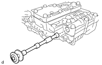
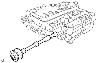
1. REMOVE MANUAL VALVE
| (a) Remove the manual valve from the transmission valve body assembly. |
|
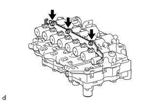
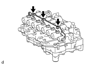
2. REMOVE SOLENOID LOCK PLATE
| (a) Remove the 3 bolts and solenoid lock plate from the transmission valve body assembly. |
|
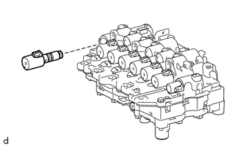
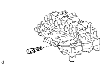
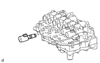
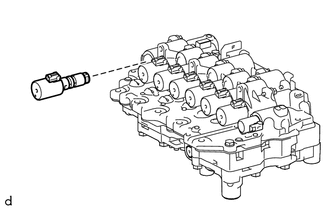
3. REMOVE SOLENOID (SLU) VALVE
| (a) Remove the solenoid (SLU) valve from the transmission valve body assembly. |
|
4. REMOVE SOLENOID (SL5) VALVE
| (a) Remove the solenoid (SL5) valve from the transmission valve body assembly. |
|
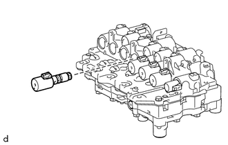
5. REMOVE SOLENOID (SL6) VALVE
| (a) Remove the solenoid (SL6) valve from the transmission valve body assembly. |
|
6. REMOVE SOLENOID (SL4) VALVE
| (a) Remove the solenoid (SL4) valve from the transmission valve body assembly. |
|
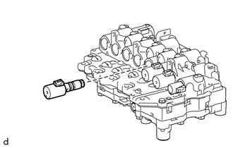
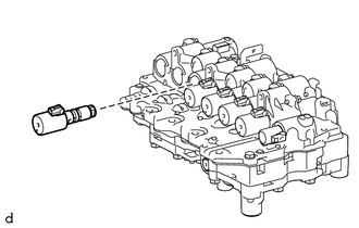
7. REMOVE SOLENOID (SL3) VALVE
| (a) Remove the solenoid (SL3) valve from the transmission valve body assembly. |
|
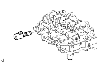
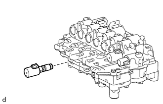
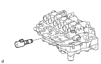
8. REMOVE SOLENOID (SL1) VALVE
| (a) Remove the solenoid (SL1) valve from the transmission valve body assembly. |
|
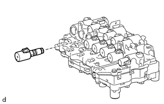
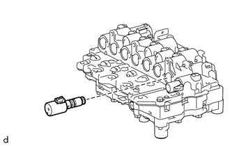
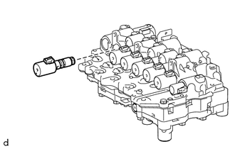
9. REMOVE SOLENOID (SL2) VALVE
| (a) Remove the solenoid (SL2) valve from the transmission valve body assembly. |
|
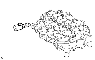
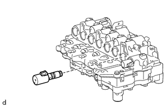
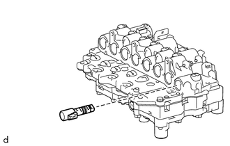
10. REMOVE SOLENOID (SLT) VALVE
| (a) Remove the solenoid (SLT) valve from the transmission valve body assembly. |
|
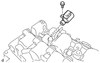
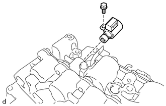
11. REMOVE SOLENOID (SL) VALVE
| (a) Remove the bolt and solenoid (SL) valve from the transmission valve body assembly. |
|
Inspection
INSPECTION
PROCEDURE
1. INSPECT SOLENOID (SL) VALVE
| (a) Measure the resistance according to the value(s) in the table below.
Standard Resistance: |
Tester Connection | Condition |
Specified Condition | |
Solenoid (SL) valve connector terminal - Solenoid (SL) valve body |
20°C (68°F) | 11 to 15 Ω |
If the result is not as specified, replace the solenoid (SL) valve. |
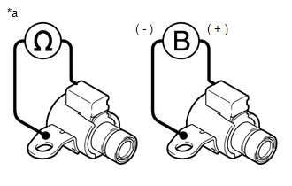 |
|
*a | Component without harness connected
(Solenoid (SL) Valve) | | |
(b)
Connect a positive (+) lead from the battery to the terminal of the
solenoid (SL) valve connector and a negative (-) lead to the solenoid
(SL) valve body, and check that the solenoid (SL) valve moves and makes
an operating sound.
NOTICE:
When
using battery voltage during the inspection, do not bring the positive
(+) and negative (-) tester probes too close to each other as a short
circuit may occur.
OK:
The solenoid (SL) valve moves and makes an operating sound.
If the result is not as specified, replace the solenoid (SL) valve.
2. INSPECT SOLENOID (SLT) VALVE
| (a) Measure the resistance according to the value(s) in the table below.
Standard Resistance: |
Tester Connection | Condition |
Specified Condition | |
1 - 2 | 20°C (68°F) |
5.0 to 5.6 Ω | If the result is not as specified, replace the solenoid (SLT) valve. |
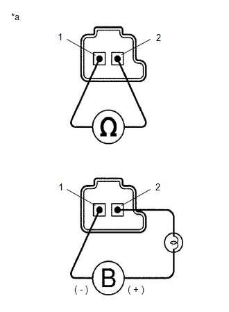 |
|
*a | Component without harness connected
(Solenoid (SLT) Valve) | | |
(b)
Connect a positive (+) lead from the battery with a 21 W bulb to
terminal 2 and a negative (-) lead to terminal 1 of the solenoid (SLT)
valve connector, and check that the solenoid (SLT) valve moves and makes
an operating sound.
NOTICE:
When
using battery voltage during the inspection, do not bring the positive
(+) and negative (-) tester probes too close to each other as a short
circuit may occur.
OK:
The solenoid (SLT) valve moves and makes an operating sound.
If the result is not as specified, replace the solenoid (SLT) valve.
3. INSPECT SOLENOID (SLU) VALVE
HINT:
Refer to Inspect Solenoid (SLT) Valve.
4. INSPECT SOLENOID (SL1) VALVE
HINT:
Refer to Inspect Solenoid (SLT) Valve.
5. INSPECT SOLENOID (SL2) VALVE
HINT:
Refer to Inspect Solenoid (SLT) Valve.
6. INSPECT SOLENOID (SL3) VALVE
HINT:
Refer to Inspect Solenoid (SLT) Valve.
7. INSPECT SOLENOID (SL4) VALVE
HINT:
Refer to Inspect Solenoid (SLT) Valve.
8. INSPECT SOLENOID (SL5) VALVE
HINT:
Refer to Inspect Solenoid (SLT) Valve.
9. INSPECT SOLENOID (SL6) VALVE
HINT:
Refer to Inspect Solenoid (SLT) Valve.
Installation
INSTALLATION
PROCEDURE
1. INSTALL TRANSMISSION VALVE BODY ASSEMBLY
(a) Coat 2 new transaxle case gaskets with Toyota Genuine ATF WS and install them to the automatic transaxle case sub-assembly.
(b) Coat a new transaxle case gasket with Toyota Genuine ATF WS and install it to the counter drive gear sub-assembly.
(c) Coat a new No. 1 front oil pump cover gasket with Toyota Genuine ATF WS and install it to the front oil pump assembly.
(d) Coat a new No. 2 front oil pump cover gasket with Toyota Genuine ATF WS and install it to the front oil pump assembly.
| (e)
Align the slit portion of the manual valve and the manual valve lever
sub-assembly as shown in the illustration, and install the transmission
valve body assembly to the automatic transaxle case sub-assembly with
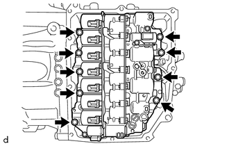
the 9 bolts. Torque: 10.8 N·m {110 kgf·cm, 8 ft·lbf} NOTICE:
Be careful that the transmission revolution sensor (NC) wire is not pinched. |
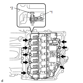 |
|
*1 | Manual Valve | |
*2 | Manual Valve Lever Sub-assembly | | |
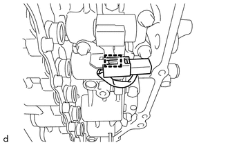
(f) Engage the clamp to connect the transmission revolution sensor (NC) wire connector.
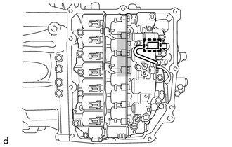
 |
Do not let transmission revolution sensor (NC) wire ride up over this area. |
NOTICE:
To
prevent it from being pinched between the transmission valve body
assembly and the transmission case side cover, do not let the
transmission revolution sensor (NC) wire ride up over the area shown in
the illustration.
2. INSTALL TRANSMISSION WIRE
Click here

3. CHECK AUTOMATIC TRANSAXLE SYSTEM
NOTICE:
If
automatic transaxle parts have been replaced, refer to Parts
Replacement Compensation Table to determine if any additional operations
are necessary.
Click here 
Reassembly
REASSEMBLY
PROCEDURE
1. INSTALL SOLENOID (SL) VALVE
| (a) Coat the solenoid (SL) valve with Toyota Genuine ATF WS. |
|
(b) Install the solenoid (SL) valve to the transmission valve body assembly with the bolt.
Torque:
7.0 N·m {71 kgf·cm, 62 in·lbf}
2. INSTALL SOLENOID (SLT) VALVE
| (a) Coat the solenoid (SLT) valve with Toyota Genuine ATF WS and install it to the transmission valve body assembly. |
|
3. INSTALL SOLENOID (SL2) VALVE
| (a) Coat the solenoid (SL2) valve with Toyota Genuine ATF WS and install it to the transmission valve body assembly. |
|
4. INSTALL SOLENOID (SL1) VALVE
| (a) Coat the solenoid (SL1) valve with Toyota Genuine ATF WS and install it to the transmission valve body assembly. |
|
5. INSTALL SOLENOID (SL3) VALVE
| (a) Coat the solenoid (SL3) valve with Toyota Genuine ATF WS and install it to the transmission valve body assembly. |
|
6. INSTALL SOLENOID (SL4) VALVE
| (a) Coat the solenoid (SL4) valve with Toyota Genuine ATF WS and install it to the transmission valve body assembly. |
|
7. INSTALL SOLENOID (SL6) VALVE
| (a) Coat the solenoid (SL6) valve with Toyota Genuine ATF WS and install it to the transmission valve body assembly. |
|
8. INSTALL SOLENOID (SL5) VALVE
| (a) Coat the solenoid (SL5) valve with Toyota Genuine ATF WS and install it to the transmission valve body assembly |
|
9. INSTALL SOLENOID (SLU) VALVE
| (a) Coat the solenoid (SLU) valve with Toyota Genuine ATF WS and install it to the transmission valve body assembly. |
|
10. INSTALL SOLENOID LOCK PLATE
| (a) Install the solenoid lock plate to the transmission valve body assembly with the 3 bolts.
Torque: 7.0 N·m {71 kgf·cm, 62 in·lbf} | |
11. INSTALL MANUAL VALVE
|
(a) Coat the manual valve with Toyota Genuine ATF WS and install it to the transmission valve body assembly. |
|
Removal
REMOVAL
CAUTION / NOTICE / HINT
The
necessary procedures (adjustment, calibration, initialization or
registration) that must be performed after parts are removed and
installed, or replaced during transmission valve body assembly
removal/installation are shown below.
Necessary Procedures After Parts Removed/Installed/Replaced |
Replaced Part or Performed Procedure |
Necessary Procedure | Effect/Inoperative Function when Necessary Procedure not Performed |
Link |
- Transmission valve body assembly
- Solenoid (SL1, SL2, SL3, SL4, SL5 and/or SL6) valve
|
- Perform reset memory
- Reset transaxle compensation code
- Perform road test to allow ECM to learn
|
- Large shift shock
- Deterioration of fuel efficiency
|
 for Initialization for Initialization
 for Registration for Registration |
PROCEDURE
1. REMOVE TRANSMISSION WIRE
Click here 
2. REMOVE TRANSMISSION VALVE BODY ASSEMBLY
| (a) Disengage the clamp to disconnect the transmission revolution sensor (NC) wire connector. |
|
| (b) Remove the 9 bolts and transmission valve body assembly from the automatic transaxle case sub-assembly. |
|
| (c) Remove the 2 transaxle case gaskets from the automatic transaxle case sub-assembly. |
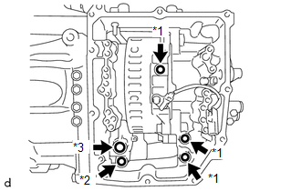 |
|
*1 | Transaxle Case Gasket | |
*2 | No. 1 Front Oil Pump Cover Gasket | |
*3 | No. 2 Front Oil Pump Cover Gasket | | |
(d) Remove the transaxle case gasket from the counter drive gear sub-assembly.
(e) Remove the No. 1 front oil pump cover gasket from the front oil pump assembly.
(f) Remove the No. 2 front oil pump cover gasket from the front oil pump assembly.




 for Initialization
 for Registration
