SYSTEM DESCRIPTION SYSTEM DESCRIPTION (a)
The Electronic Controlled Automatic Transaxle (ECT) is an automatic
transaxle that electronically controls shift timing using the ECM. The
ECM detects electrical signals that indicate engine and driving
conditions, and controls shift points based on driver habits and road
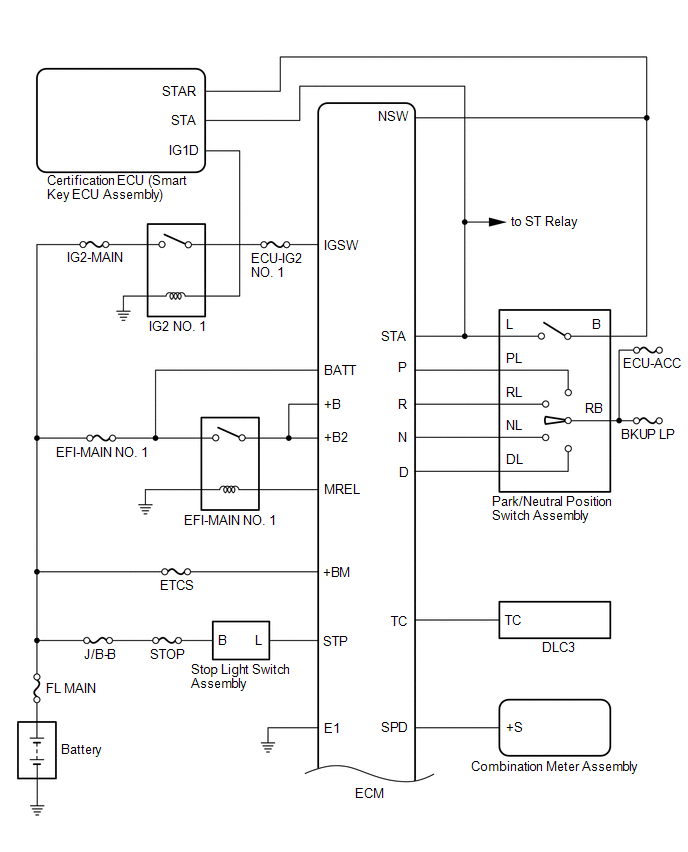
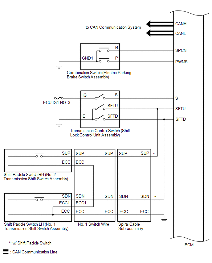
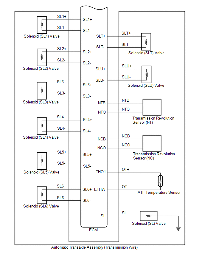
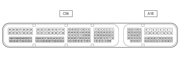
conditions. Shift shock is reduced by controlling the engine and transaxle simultaneously. In addition, the ECT has the following features: SYSTEM DIAGRAM TERMINALS OF ECM ECM HINT: The standard voltage and resistance of each ECM terminal is shown in the table below. In
the table, first follow the information under "Condition". Look under
"Terminal No. (Symbol)" for the terminals to be inspected. The standard
voltage or resistance between the terminals is shown under "Specified
Condition". Use the illustration above as a reference for the ECM terminals. Terminal No. (Symbol) Wiring Color Terminal Description Condition Specified Condition A18-1 (BATT) - C56-53 (E1) R - W-B Battery (for measuring battery voltage and for ECM memory) Always 11 to 14 V A18-2 (+B) - C56-53 (E1) L - W-B Power source of ECM Engine switch on (IG) 11 to 14 V A18-3 (+B2) - C56-53 (E1) L - W-B Power source of ECM Engine switch on (IG) 11 to 14 V A18-8 (+BM) - C56-53 (E1) G - W-B Power source of ECM Always 11 to 14 V A18-13 (CANH) - C56-53 (E1) B - W-B CAN communication line Engine switch on (IG) Pulse generation A18-17 (S) - C56-53 (E1) GR - W-B S shift position switch signal Engine switch on (IG) and shift lever in S 11 to 14 V Engine switch on (IG) and shift lever not in S Below 1 V A18-26 (CANL) - C56-53 (E1) W - W-B CAN communication line Engine switch on (IG) Pulse generation A18-27 (STP) - C56-53 (E1) SB - W-B Stop light switch signal Brake pedal depressed 7.5 to 14 V Brake pedal released Below 1 V A18-37 (SFTD) - C56-53 (E1) W - W-B Down-shift switch signal Engine switch on (IG) 11 to 14 V Engine switch on (IG) and shift lever held in "-" (Down shift) Below 1 V Engine switch on (IG) and "-" (Down shift) shift paddle switch operated Below 1 V A18-38 (SFTU) - C56-53 (E1) G - W-B Up-shift switch signal Engine switch on (IG) 11 to 14 V Engine switch on (IG) and shift lever held in "+" (Up shift) Below 1 V Engine switch on (IG) and "+" (Up shift) shift paddle switch operated Below 1 V A18-39 (SPD) - C56-53 (E1) L - W-B Vehicle speed signal from combination meter assembly Driving at 20 km/h (12 mph) Pulse generation A18-40 (SPCN) - C56-53 (E1) V - W-B Combination switch (NORMAL) signal Engine switch on (IG) and combination switch (NORMAL) being pushed and held Below 1.5 V Engine switch on (IG) and combination switch (NORMAL) not pushed 11 to 14 V A18-43 (STA) - C56-53 (E1) G - W-B Starter signal Cranking (shift lever in P or N, engine switch on (START)) 11 to 14 V Engine switch on (IG) and shift lever in P or N Below 2 V A18-55 (PWMS) - C56-53 (E1) LG - W-B Combination switch (SPORT) signal Engine switch on (IG) and combination switch (SPORT) being pushed and held Below 1.5 V Engine switch on (IG) and combination switch (SPORT) not pushed 11 to 14 V C56-6 (SL3+) - C56-7 (SL3-) L - R Solenoid (SL3) valve signal 3rd, 7th or Reverse gear Pulse generation C56-10 (SL5+) - C56-11 (SL5-) W - R Solenoid (SL5) valve signal 2nd or 8th gear Pulse generation C56-12 (SL1+) - C56-13 (SL1-) G - BR Solenoid (SL1) valve signal 1st, 2nd, 3rd, 4th or 5th gear Pulse generation C56-14 (SL4+) - C56-15 (SL4-) LG - R Solenoid (SL4) valve signal 4th or 6th gear Pulse generation C56-31 (SL2+) - C56-1 (SL2-) LG - P Solenoid (SL2) valve signal 5th, 6th, 7th or 8th gear Pulse generation C56-32 (SL6+) - C56-33 (SL6-) GR - LG Solenoid (SL6) valve signal 1st or Reverse gear Pulse generation C56-53 (E1) - Body ground W-B - Body ground Ground Always Below 1 Ω C56-62 (SL) - C56-53 (E1) W - W-B Solenoid (SL) valve signal 11 to 14 V C56-67 (SLT+) - C56-37 (SLT-) G - B Solenoid (SLT) valve signal Engine idling Pulse generation C56-72 (NCO) - C56-53 (E1) L - W-B Transmission Revolution Sensor (NC) signal Vehicle being driven Pulse generation C56-73 (NCB) - C56-53 (E1) G - W-B Power source for sensor (specific voltage) Engine switch on (IG) 11 to 14 V C56-74 (NTO) - C56-53 (E1) B - W-B Transmission Revolution Sensor (NT) signal Engine idling (shift lever in P or N) Pulse generation C56-75 (NTB) - C56-53 (E1) R - W-B Power source for sensor (specific voltage) Engine switch on (IG) 11 to 14 V C56-76 (SLU+) - C56-61 (SLU-) L - B Solenoid (SLU) valve signal Lock-up ON Pulse generation C56-86 (THO1) - C56-133 (ETHW) W - BR ATF temperature sensor signal ATF temperature 115°C (239°F) or higher Below 1.5 V C56-106 (NSW) - C56-53 (E1) R - W-B Park/neutral position switch signal Engine switch on (IG) and shift lever in P or N Below 1 V Engine switch on (IG) and shift lever not in P or N 11 to 14 V C56-107 (R) - C56-53 (E1) W - W-B R shift position switch signal Engine switch on (IG) and shift lever in R 11 to 14 V Engine switch on (IG) and shift lever not in R Below 1 V C56-108 (P) - C56-53 (E1) B - W-B P shift position switch signal Engine switch on (IG) and shift lever in P 11 to 14 V Engine switch on (IG) and shift lever not in P Below 1 V C56-139 (D) - C56-53 (E1) R - W-B D shift position switch signal Engine switch on (IG) and shift lever in D or S 11 to 14 V Engine switch on (IG) and shift lever not in D or S Below 1 V C56-140 (N) - C56-53 (E1) LG - W-B N shift position switch signal Engine switch on (IG) and shift lever in N 11 to 14 V Engine switch on (IG) and shift lever not in N Below 1 VSystem Description
System Diagram


Terminals Of Ecm

Toyota Avalon (XX50) 2019-2022 Service & Repair Manual > 2gr-fks Engine Control: Ignition Coil And Spark Plug
ComponentsCOMPONENTS ILLUSTRATION *1 IGNITION COIL ASSEMBLY *2 SPARK PLUG *3 V-BANK COVER SUB-ASSEMBLY *4 VACUUM HOSE N*m (kgf*cm, ft.*lbf): Specified torque - - InstallationINSTALLATION PROCEDURE 1. INSTALL SPARK PLUG Click here 2. INSTALL IGNITION COIL ASSEMBLY HINT: Perform "Inspection After Rep ...