Registration
REGISTRATION
CAUTION / NOTICE / HINT
NOTICE:
- When the automatic transaxle assembly is replaced, the transaxle
compensation code must be registered to the ECM (proceed to Procedure
1).
After the automatic transaxle assembly is installed,
the Quick Response (QR) code label will be positioned where the code
cannot be read. Therefore, before installing the automatic transaxle
assembly, record the transaxle compensation code or register it using
the Techstream.
- When the ECM is replaced, the existing transaxle compensation code must be registered to the new ECM (proceed to Procedure 2).
- Perform Reset Memory (AT initialization) after replacing the automatic
transaxle assembly, transmission valve body assembly, any of the
solenoid valves or engine assembly.
PROCEDURE
1. INPUT TRANSAXLE COMPENSATION CODE INTO ECM (Procedure 1)
NOTICE:
Transaxle
compensation codes are unique, 60-digit alphanumeric values printed on a
QR code label on the transaxle. If an incorrect transaxle compensation
code is registered to the ECM, shift shock may occur.
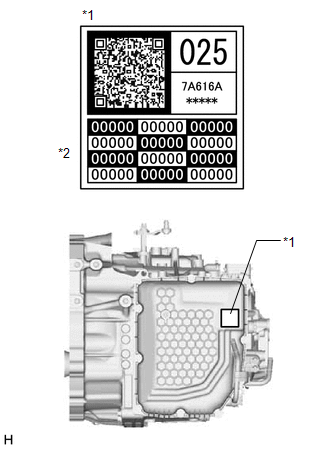
| (a) Record the transaxle compensation code specified on the QR code label.
HINT: The transaxle compensation code is printed on the QR code label. |
 |
|
*1 | QR Code Label | |
*2 | Transaxle Compensation Code | | |
(b) Make sure the shift lever is in P or N.
(c) Connect the Techstream to the DLC3.
(d) Turn the engine switch on (IG).
NOTICE:
Do not start the engine.
(e) Turn the Techstream on.
(f) Enter the following menus: Powertrain / Transmission / Utility / A/T Code Registration.
Powertrain > Transmission > Utility
|
Tester Display |
| A/T Code Registration |
(g) Select "Set Compensation Code".
(h) Register the transaxle compensation code.
(1) Press "Input".
(2)
Manually input the transaxle compensation code. The code is a 60-digit
alphanumeric value printed on the QR code label. After inputting the
code, press "OK".
(i) Check that the transaxle
compensation code displayed on the screen is correct by comparing it
with the 60-digit alphanumeric value on the QR code label.
NOTICE:
If an incorrect transaxle compensation code is registered to the ECM, shift shock may occur.
(j) Press "NEXT" to register the transaxle compensation code to the ECM.
NOTICE:
- If the registration process fails, the transaxle compensation code may
be incorrect. Check the transaxle compensation code again.
- If the attempted transaxle compensation code is correct, a problem with
the wire harness or a bad connection with the DLC3 may cause
registration failure. Check the wire harness and the DLC3 connection. If
no problem is found, the ECM may be malfunctioning. Check the ECM and
repeat this operation.
2. TRANSFER TRANSAXLE COMPENSATION CODE (Procedure 2)
NOTICE:
Transaxle
compensation codes are unique, 60-digit alphanumeric values printed on a
QR code label on the transaxle. If an incorrect transaxle compensation
code is registered to the ECM, shift shock may occur.
HINT:
The
following operation is available for use when the ECM that is being
replaced can still transmit its registered transaxle compensation code
to the Techstream.
(a) Read the transaxle compensation code.
(1) Make sure the shift lever is in P or N.
(2) Connect the Techstream to the DLC3.
(3) Turn the engine switch on (IG).
NOTICE:
Do not start the engine
(4) Turn the Techstream on.
(5) Enter the following menus: Powertrain / Transmission / Utility / A/T Code Registration.
Powertrain > Transmission > Utility
|
Tester Display |
| A/T Code Registration |
(6) Select "Read Compensation Code".
(7) Press "Save".
(8) Press "Save" or "Overwrite".
(9) Press "Exit".
NOTICE:
Do
not use the code printed on the transaxle QR code label even if the
transaxle compensation code cannot be read using the Techstream. The
code printed on an in-service transaxle may not match its current
characteristics. Replace the ECM with a new one and perform a road test
to allow the ECM to learn the transaxle characteristics.
(10) Turn the engine switch off.
(b) Replace the ECM.
(c) Register the transaxle compensation code.
(1) Turn the engine switch on (IG).
NOTICE:
Do not start the engine.
(2) Turn the Techstream on.
(3) Enter the following menus: Powertrain / Transmission / Utility / A/T Code Registration.
Powertrain > Transmission > Utility
|
Tester Display |
| A/T Code Registration |
(4) Select "Set Compensation Code".
(5) Press "Open".
(6) Press "Open" again to proceed.
(7) Press "EXIT".
Road Test
ROAD TEST
PROBLEM SYMPTOM CONFIRMATION
(a)
Based on the result of the customer problem analysis, try to reproduce
the symptoms. If the problem is that the transaxle does not shift up,
shift down, or the shift point is too high or too low, conduct the
following road test referring to the automatic shift schedule and
simulate the problem symptoms.
ROAD TEST
CAUTION:
- Strictly obey all traffic rules and regulations.
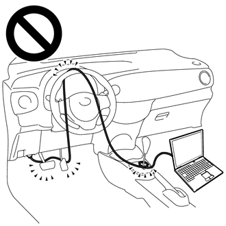
- Do not drive the vehicle with the Techstream cable contacting the pedals, shift lever or steering wheel.
- Driving the wheel with the Techstream cable contacting these areas could
impede vehicle control, resulting in a serious accident.
- Do not operate the Techstream while driving the vehicle.
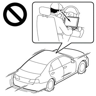
- Operating the Techstream while driving the vehicle will prevent you from
paying sufficient attention to vehicle surroundings, and could result
in a serious accident.
NOTICE:
- Be sure to inspect and adjust the engine before performing these tests.
- Perform the road test with the engine coolant temperature between 60 and
100°C (140 and 212°F) and the ATF temperature between 50 and 100°C (122
and 212°F).
- Perform these tests with the air conditioning and cruise control off.
|
Inspection |
Procedure |
|
Transmission Control Switch Test |
With
the vehicle stationary and the shift lever in D, move the shift lever
to S and return it to D. Check that the meter display changes from D to
the appropriate S gear and then back again. |
|
S Position Test |
While driving with the shift lever in S, move the shift lever to "+" and "-". Check that the meter display changes accordingly.
|
|
D Position Shift Test |
While driving the vehicle normally, check that the transaxle shifts up and down through each gear properly.
|
|
Lock-up Function |
While
driving on a level surface at a constant speed in the lock-up range
with the shift lever in D, lightly depress the accelerator pedal and
check that the engine speed does not change abruptly. |
|
P Position Test |
Stop
the vehicle on an incline (approximately 5° or more). Then move the
shift lever to P and release the parking brake. Check that the parking
lock pawl holds the vehicle in place. |
|
Abnormal Noise and Vibration |
Check for abnormal noise and vibration while driving the vehicle forward and backward, and during shift operations.
|
|
Fluid Leakage |
After performing all other road test inspections, check for fluid leakage.
|
HINT:
When checking for DTCs after a repair, drive the vehicle according to the monitor drive pattern.
Click here 
(a) Gear change confirmation
(1) Connect the Techstream to the DLC3.
(2) Turn the engine switch on (IG).
(3) Enter the following menus: Powertrain / Transmission / Data List.
Powertrain > Transmission > Data List
|
Tester Display |
| Vehicle Speed |
|
Coolant Temperature |
|
NT Sensor Speed |
|
A/T Oil Temperature No.1 |
|
Shift Status |
(4) Check that the transaxle shifts to each gear while gently accelerating to 85 km/h (53 mph) or higher.
HINT:
- Check that the value of NT Sensor Speed drops by 50 rpm or more when the value of Shift Status increases.
- Depending on the engine speed when the gear is changed, it may be difficult to see the change of NT Sensor Speed.
(b) Lock-up confirmation
(1) Connect the Techstream to the DLC3.
(2) Turn the engine switch on (IG).
(3) Enter the following menus: Powertrain / Transmission / Data List.
Powertrain > Transmission > Data List
|
Tester Display |
| Vehicle Speed |
|
Engine Speed |
| Coolant Temperature |
|
Accel Position from EFI |
|
NT Sensor Speed |
|
A/T Oil Temperature No.1 |
|
Lock Up Status |
|
Shift Status |
(4) When the following conditions are met, check that the difference between Engine Speed and NT Sensor Speed is 50 rpm or less.
Lock-up Schedule:
|
Vehicle Speed (Constant speed) |
85 km/h (53 mph) |
| Shift Status |
8th |
| Lock Up Status |
ON |
HINT:
- If Lock Up Status does not change to ON, decrease the accelerator pedal opening angle or increase the vehicle speed.
- Lock-up will not be engaged if the accelerator pedal is released.
- Lock-up prohibition conditions:
- Engine coolant temperature is less than 20°C (68°F)
- ATF temperature is less than 20°C (68°F) or higher than 110°C (230°F)
- Throttle valve is fully closed
- Stop light switch is on
Shift Paddle Switch Circuit
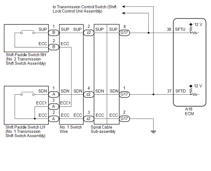
DESCRIPTION
Moving the
shift lever to S enables the shift range to be selected. The shift range
can be selected by operating the "+" or "-" shift paddle switch.
WIRING DIAGRAM
CAUTION / NOTICE / HINT
NOTICE:
After
turning the engine switch off, waiting time may be required before
disconnecting the cable from the negative (-) battery terminal.
Therefore, make sure to read the disconnecting the cable from the
negative (-) battery terminal notices before proceeding with work.
Click here

PROCEDURE
| 1. |
READ VALUE USING TECHSTREAM (SPORT SHIFT SWITCH STATUS) |
(a) Connect the Techstream to the DLC3.
(b) Turn the engine switch on (IG).
(c) Turn the Techstream on.
(d) Enter the following menus: Powertrain / Engine / Data List.
(e) According to the display on the Techstream, read the Data List.
Powertrain > Engine > Data List
|
Tester Display | Measurement Item |
Range | Normal Condition |
Diagnostic Note |
|
Sport Shift Up SW | Sport shift up switch status |
ON or OFF |
- ON: Shift lever held in "+" or "+" shift paddle switch operated
- OFF: Shift lever not held in "+" and "+" shift paddle switch released
| - |
|
Sport Shift Down SW | Sport shift down switch status |
ON or OFF |
- ON: Shift lever held in "-" or "-" shift paddle switch operated
- OFF: Shift lever not held in "-" and "-" shift paddle switch released
| - |
Powertrain > Engine > Data List
|
Tester Display |
| Sport Shift Up SW |
|
Sport Shift Down SW |
|
Result | Proceed to |
|
Data List values are normal |
A |
| Data List values are not normal |
B |
| A |
 | CHECK FOR INTERMITTENT PROBLEMS |
|
B |
 | |
| 2. |
CHECK HARNESS AND CONNECTOR (SHIFT PADDLE SWITCH CIRCUIT) |
(a) Disconnect the A18 ECM connector.
(b) Measure the resistance according to the value(s) in the table below.
Standard Resistance:
|
Tester Connection | Condition |
Specified Condition |
|
A18-38 (SFTU) - Body ground |
"+" (Up shift) shift paddle switch operated and held |
Below 13 Ω |
|
"+" (Up shift) shift paddle switch not operated |
10 kΩ or higher |
|
A18-37 (SFTD) - Body ground |
"-" (Down shift) shift paddle switch operated and held |
Below 13 Ω |
|
"-" (Down shift) shift paddle switch not operated |
10 kΩ or higher |
| OK |
 | PROCEED TO NEXT SUSPECTED AREA SHOWN IN PROBLEM SYMPTOMS TABLE |
|
NG |
 | |
| 3. |
CHECK HARNESS AND CONNECTOR (SPIRAL CABLE SUB-ASSEMBLY - ECM) |
(a) Disconnect the G17 spiral cable sub-assembly connector.
(b) Disconnect the A18 ECM connector.
(c) Measure the resistance according to the value(s) in the table below.
Standard Resistance:
|
Tester Connection | Condition |
Specified Condition |
|
A18-38 (SFTU) - G17-8 (SUP) |
Always | Below 1 Ω |
|
A18-37 (SFTD) - G17-1 (SDN) |
Always | Below 1 Ω |
|
A18-38 (SFTU) or G17-8 (SUP) - Body ground |
Always | 10 kΩ or higher |
|
A18-37 (SFTD) or G17-1 (SDN) - Body ground |
Always | 10 kΩ or higher |
| NG |
 | REPAIR OR REPLACE HARNESS OR CONNECTOR (SPIRAL CABLE SUB-ASSEMBLY - ECM) |
|
OK |
 | |
| 4. |
CHECK HARNESS AND CONNECTOR (SPIRAL CABLE SUB-ASSEMBLY - BODY GROUND) |
(a) Disconnect the G17 spiral cable sub-assembly connector.
(b) Measure the resistance according to the value(s) in the table below.
Standard Resistance:
|
Tester Connection | Condition |
Specified Condition |
|
G17-2 (ECC) - Body ground |
Always | Below 1 Ω |
| NG |
 | REPAIR OR REPLACE HARNESS OR CONNECTOR (SPIRAL CABLE SUB-ASSEMBLY - BODY GROUND) |
|
OK |
 | |
| 5. |
INSPECT SPIRAL CABLE SUB-ASSEMBLY |
(a) Inspect the spiral cable sub-assembly.
Click here 
| NG |
 | REPLACE SPIRAL CABLE SUB-ASSEMBLY |
|
OK |
 | |
| 6. |
INSPECT SHIFT PADDLE SWITCH LH (NO. 1 TRANSMISSION SHIFT SWITCH ASSEMBLY) |
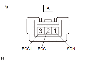
| (a) Remove the shift paddle switch LH (No. 1 transmission shift switch assembly).
Click here  |
 |
|
*a | Component without harness connected
(Shift Paddle Switch LH (No. 1 Transmission Shift Switch Assembly)) | | |
(b) Measure the resistance according to the value(s) in the table below.
Standard Resistance:
|
Tester Connection | Condition |
Specified Condition |
|
A-1 (SDN) - A-2 (ECC) |
"-" (Down shift) shift paddle switch operated and held |
Below 13 Ω |
|
"-" (Down shift) shift paddle switch not operated |
10 kΩ or higher |
|
A-1 (SDN) - A-3 (ECC1) |
"-" (Down shift) shift paddle switch operated and held |
Below 13 Ω |
|
"-" (Down shift) shift paddle switch not operated |
10 kΩ or higher |
| NG |
 | REPLACE SHIFT PADDLE SWITCH LH (NO. 1 TRANSMISSION SHIFT SWITCH ASSEMBLY) |
|
OK |
 | |
| 7. |
INSPECT SHIFT PADDLE SWITCH RH (NO. 2 TRANSMISSION SHIFT SWITCH ASSEMBLY) |
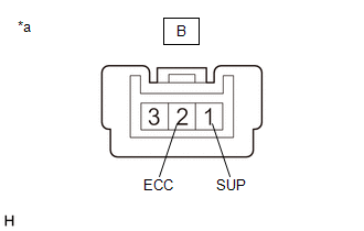
| (a) Remove the shift paddle switch RH (No. 2 transmission shift switch assembly).
Click here  |
 |
|
*a | Component without harness connected
(Shift Paddle Switch RH (No. 2 Transmission Shift Switch Assembly)) | | |
(b) Measure the resistance according to the value(s) in the table below.
Standard Resistance:
|
Tester Connection | Condition |
Specified Condition |
|
B-1 (SUP) - B-2 (ECC) |
"+" (Up shift) shift paddle switch operated and held |
Below 13 Ω |
|
"+" (Up shift) shift paddle switch not operated |
10 kΩ or higher |
| NG |
 | REPLACE SHIFT PADDLE SWITCH RH (NO. 2 TRANSMISSION SHIFT SWITCH ASSEMBLY) |
|
OK |
 | |
| 8. |
INSPECT NO. 1 SWITCH WIRE |
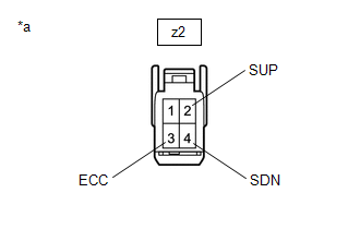
| (a) Install the No. 1 and No. 2 transmission shift switch assemblies.
Click here  |
 |
|
*a | Front view of wire harness connector
(to Spiral Cable Sub-assembly) | | |
(b) Disconnect the z2 No. 1 switch wire connector.
(c) Measure the resistance according to the value(s) in the table below.
Standard Resistance:
|
Tester Connection | Condition |
Specified Condition |
|
z2-2 (SUP) - z2-3 (ECC) |
"+" (Up shift) shift paddle switch operated and held |
Below 13 Ω |
|
"+" (Up shift) shift paddle switch not operated |
10 kΩ or higher |
|
z2-4 (SDN) - z2-3 (ECC) |
"-" (Down shift) shift paddle switch operated and held |
Below 13 Ω |
|
"-" (Down shift) shift paddle switch not operated |
10 kΩ or higher |
| OK |
 | PROCEED TO NEXT SUSPECTED AREA SHOWN IN PROBLEM SYMPTOMS TABLE |
| NG |
 | REPLACE NO. 1 SWITCH WIRE |


