Components
COMPONENTS
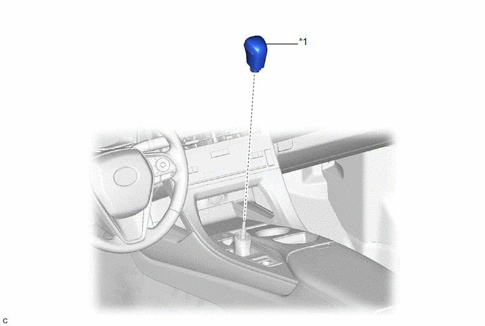
ILLUSTRATION
|
*1 | SHIFT LEVER KNOB SUB-ASSEMBLY |
- | - |
Installation
INSTALLATION
PROCEDURE
1. INSTALL SHIFT LEVER KNOB SUB-ASSEMBLY
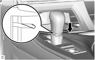
| (a) Install the shift lever knob sub-assembly to the transmission floor shift assembly. |
|
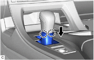
| (b) Engage the 2 claws to connect the shifting hole cover sub-assembly as shown in the illustration. NOTICE: Make sure that the shifting hole cover sub-assembly does not twist after installing the shift lever knob sub-assembly. |
|
Removal
REMOVAL
PROCEDURE
1. REMOVE SHIFT LEVER KNOB SUB-ASSEMBLY
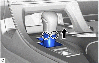
| (a) Disengage the 2 claws to disconnect the shifting hole cover sub-assembly as shown in the illustration. |
|
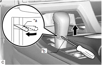
| (b) Using a screwdriver with its tip wrapped with protective tape, expand the left side of the clip and remove the shift lever knob sub-assembly from the transmission floor shift assembly as shown in the illustration. NOTICE: Be careful not to damage the shift lever knob sub-assembly. |
|
Toyota Avalon (XX50) 2019-2022 Service & Repair Manual > Audio And Visual System(for Hv Model): Steering Pad Switch Circuit. System Description. System Diagram
Steering Pad Switch Circuit DESCRIPTION This circuit sends an operation signal from the steering pad switch assembly to the radio and display receiver assembly. If there is an open in the circuit, the audio system cannot be operated using the steering pad switch assembly. If there is a short in the ...