Toyota Avalon (XX50): Oil Pump
Components
COMPONENTS
ILLUSTRATION
|
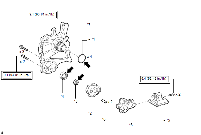
*1 | CLUTCH DRUM OIL SEAL RING |
*2 | FRONT OIL PUMP BODY |
|
*3 | FRONT OIL PUMP DRIVE GEAR |
*4 | FRONT OIL PUMP DRIVEN GEAR |
|
*5 | OIL STRAINER ASSEMBLY |
*6 | RING PIN |
|
*7 | STATOR SHAFT ASSEMBLY |
*8 | FRONT OIL PUMP COVER SUB-ASSEMBLY |
 |
Tightening torque for "Major areas involving basic vehicle performance such as moving/turning/stopping": N*m (kgf*cm, ft.*lbf) |
â—Ź | Non-reusable part |
 |
Toyota Genuine ATF WS |
 |
MP grease |
Disassembly
DISASSEMBLY
PROCEDURE
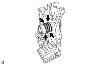
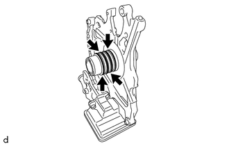
1. REMOVE CLUTCH DRUM OIL SEAL RING
| (a) Remove the 4 clutch drum oil seal rings from the stator shaft assembly. |
|
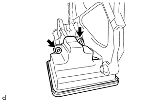
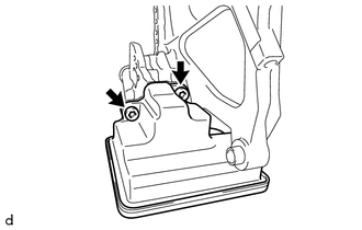
2. REMOVE OIL STRAINER ASSEMBLY
| (a) Using a T30 "TORX" socket wrench, remove the 2 bolts and oil strainer assembly from the front oil pump cover sub-assembly. |
|
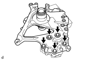
3. REMOVE STATOR SHAFT ASSEMBLY
| (a) Remove the 5 bolts and stator shaft assembly from the front oil pump body. |
|
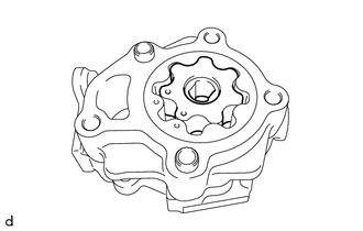
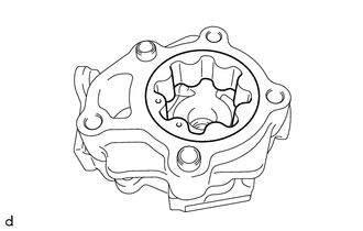
4. REMOVE FRONT OIL PUMP DRIVE GEAR
| (a) Remove the front oil pump drive gear from the front oil pump body. |
|
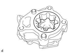
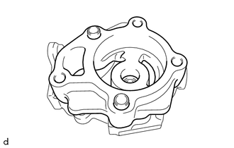
5. REMOVE FRONT OIL PUMP DRIVEN GEAR
| (a) Remove the front oil pump driven gear from the front oil pump body. |
|
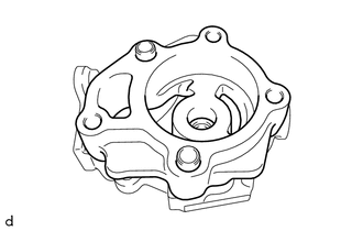
6. REMOVE FRONT OIL PUMP BODY
| (a) Remove the front oil pump body from the front oil pump cover sub-assembly. |
|
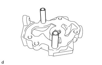
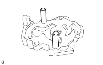
7. REMOVE RING PIN
| (a) Remove the 2 ring pins from the front oil pump cover sub-assembly. |
|
Inspection
INSPECTION
PROCEDURE
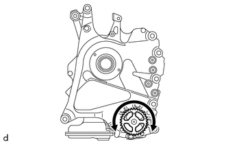
1. INSPECT FRONT OIL PUMP ASSEMBLY
| (a) Install the oil pump drive shaft sub-assembly to the front oil pump assembly.
NOTICE:
- To avoid damaging the bush of the front oil pump assembly, install the
oil pump drive shaft sub-assembly perpendicularly relative to the front
oil pump assembly.
- Align the cutout of the oil pump drive shaft sub-assembly and the cutout
of the front oil pump drive gear, and install the parts.
| |
(b) Make sure that the oil pump drive shaft sub-assembly rotates smoothly.
If
the oil pump drive shaft sub-assembly does not rotate smoothly, inspect
the front oil pump drive gear and front oil pump driven gear and front
oil pump body.
(c) Remove the oil pump drive shaft sub-assembly from the front oil pump assembly.
NOTICE:
To
avoid damaging the bush of the front oil pump assembly, remove the oil
pump drive shaft sub-assembly perpendicularly relative to the front oil
pump assembly.
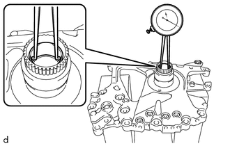
2. INSPECT STATOR SHAFT ASSEMBLY
| (a)
Using a caliper gauge, measure the inside diameter of the bushing of
the stator shaft assembly (for torque converter assembly). Standard Inside Diameter:
25.201 to 25.227 mm (0.992 to 0.993 in.) Maximum Inside Diameter:
25.227 mm (0.993 in.) If the inside diameter is more than the maximum, replace the stator shaft assembly. |
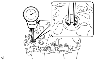
|
| (b)
Using a caliper gauge, measure the inside diameter of the bushing of
the stator shaft assembly (for oil pump drive shaft sub-assembly). Standard Inside Diameter:
12.020 to 12.035 mm (0.473 to 0.474 in.) Maximum Inside Diameter:
12.035 mm (0.474 in.) If the inside diameter is more than the maximum, replace the stator shaft assembly. |
|
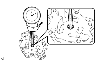
3. INSPECT FRONT OIL PUMP COVER SUB-ASSEMBLY
| (a) Using a caliper gauge, measure the inside diameter of the bushing of the front oil pump cover sub-assembly.
Standard Inside Diameter: 8.02 to 8.035 mm (0.31575 to 0.31634 in.)
Maximum Inside Diameter: 8.035 mm (0.31634 in.) If the inside diameter is more than the maximum, replace the front oil pump cover sub-assembly. |
|
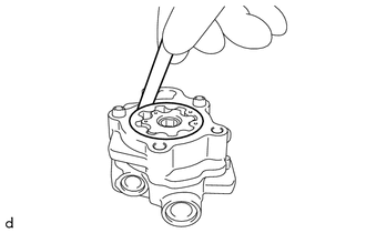
4. INSPECT FRONT OIL PUMP BODY AND GEAR SUB-ASSEMBLY
| (a) Using a feeler gauge, measure the body clearance between the front oil pump driven gear and front oil pump body.
Standard Body Clearance: 0.135 to 0.175 mm (0.00531 to 0.00689 in.)
Maximum Body Clearance: 0.175 mm (0.00689 in.) If the body clearance is more than the maximum, replace the front oil pump body and front oil pump driven gear. |
|
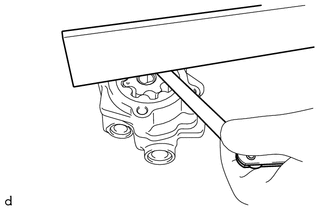
| (b) Using a straightedge and feeler gauge, measure the side clearance of both gears.
Standard Side Clearance: 0.015 to 0.034 mm (0.000591 to 0.00134 in.)
Maximum Side Clearance: 0.034 mm (0.00134 in.) If
the side clearance is more than the maximum, replace the front oil pump
body, front oil pump drive gear, front oil pump driven gear and stator
shaft assembly. | |
Reassembly
REASSEMBLY
PROCEDURE
1. INSTALL RING PIN
| (a) Install the 2 ring pins to the front oil pump cover sub-assembly. |
|
2. INSTALL FRONT OIL PUMP BODY
| (a) Install the front oil pump body to the front oil pump cover sub-assembly. |
|
3. INSTALL FRONT OIL PUMP DRIVEN GEAR
| (a) Coat the front oil pump driven gear with Toyota Genuine ATF WS and install it to the front oil pump body. |
|
4. INSTALL FRONT OIL PUMP DRIVE GEAR
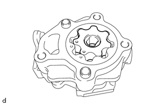
(a) Coat the front oil pump drive gear with Toyota Genuine ATF WS and install it to the front oil pump body.
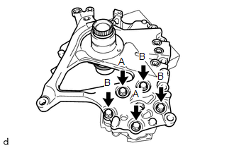
5. INSTALL STATOR SHAFT ASSEMBLY
| (a) Install the stator shaft assembly to the front oil pump body with the 5 bolts.
Torque: 9.1 N·m {93 kgf·cm, 81 in·lbf} Bolt Length: |
Bolt (A) | Bolt (B) | |
50 mm (1.97 in.) |
45 mm (1.77 in.) | | |
6. INSTALL OIL STRAINER ASSEMBLY
| (a)
Using a T30 "TORX" socket wrench, install a new oil strainer assembly
to the front oil pump cover sub-assembly with the 2 bolts. Torque:
5.4 N·m {55 kgf·cm, 48 in·lbf} | |
7. INSTALL CLUTCH DRUM OIL SEAL RING
| (a) Apply a small amount of MP grease to the entire circumference of the clutch drum oil seal ring installation groove portion.
HINT: By
applying MP grease, the wobble within the clutch drum oil seal ring
installation groove will be eliminated, preventing damage to the clutch
drum oil seal ring at the time of front oil pump assembly installation. |
|
(b) Coat 4 new clutch drum oil seal rings with Toyota Genuine ATF WS and install them to the front oil pump assembly.
NOTICE:
While
making the spread of the opening of the clutch drum oil seal ring as
small as possible, install it to the front oil pump assembly.
If the ring opening is spread, briefly hold it closed with your fingers to return it to its original condition.


