Components
COMPONENTS
ILLUSTRATION
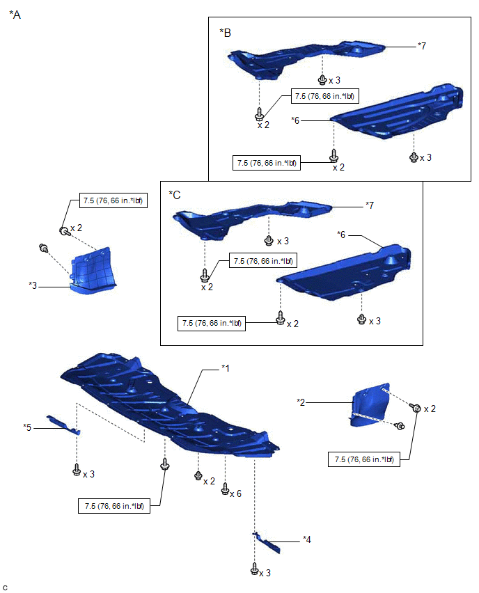
|
*A | for Gasoline Model |
*B | for Type A |
|
*C | for Type B |
- | - |
|
*1 | NO. 1 ENGINE UNDER COVER |
*2 | FRONT FENDER APRON SEAL LH |
|
*3 | FRONT FENDER APRON SEAL RH |
*4 | FRONT WHEEL OPENING EXTENSION PAD LH |
|
*5 | FRONT WHEEL OPENING EXTENSION PAD RH |
*6 | REAR ENGINE UNDER COVER LH |
|
*7 | REAR ENGINE UNDER COVER RH |
- | - |
 |
N*m (kgf*cm, ft.*lbf): Specified torque |
- | - |
ILLUSTRATION
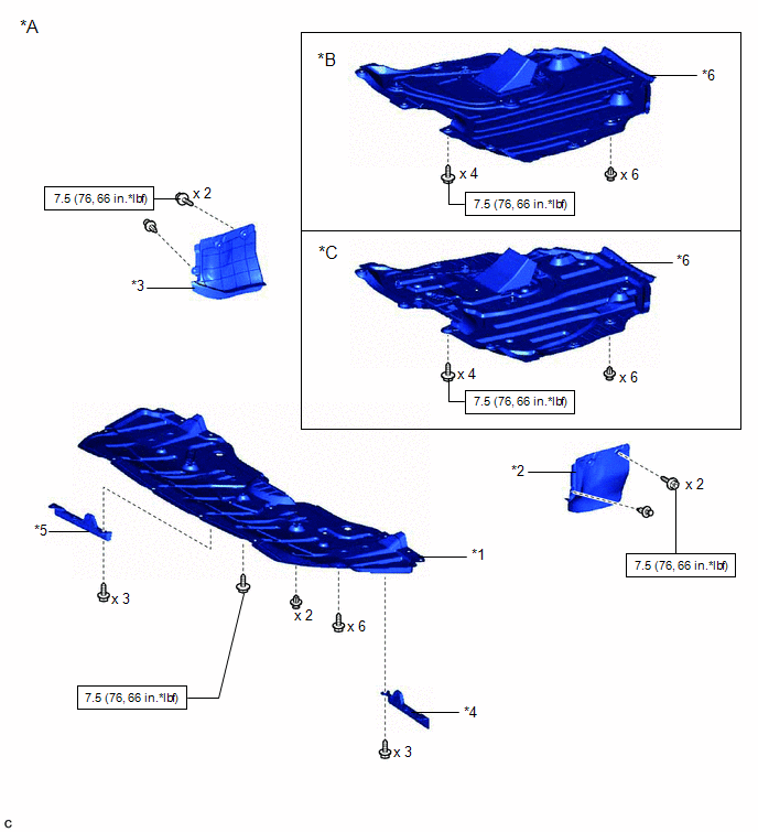
|
*A | for HV Model |
*B | for Type A |
|
*C | for Type B |
- | - |
|
*1 | NO. 1 ENGINE UNDER COVER |
*2 | FRONT FENDER APRON SEAL LH |
|
*3 | FRONT FENDER APRON SEAL RH |
*4 | FRONT WHEEL OPENING EXTENSION PAD LH |
|
*5 | FRONT WHEEL OPENING EXTENSION PAD RH |
*6 | NO. 2 ENGINE UNDER COVER ASSEMBLY |
 |
N*m (kgf*cm, ft.*lbf): Specified torque |
- | - |
ILLUSTRATION
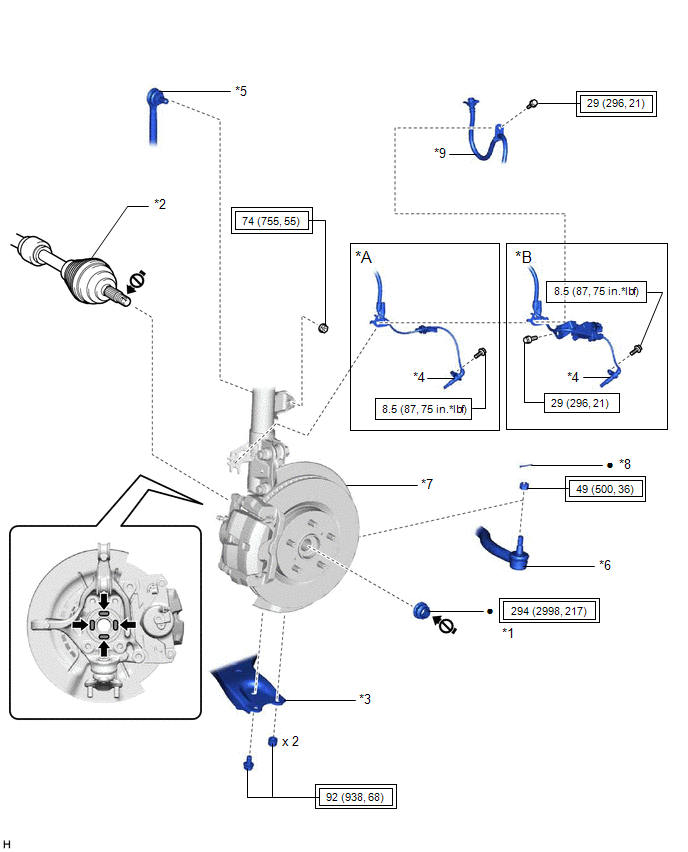
|
*A | w/o AVS |
*B | w/ AVS |
|
*1 | FRONT AXLE SHAFT NUT |
*2 | FRONT DRIVE SHAFT ASSEMBLY |
|
*3 | FRONT LOWER NO. 1 SUSPENSION ARM SUB-ASSEMBLY |
*4 | FRONT SPEED SENSOR |
|
*5 | FRONT STABILIZER LINK ASSEMBLY |
*6 | TIE ROD ASSEMBLY |
|
*7 | FRONT AXLE ASSEMBLY |
*8 | COTTER PIN |
|
*9 | FRONT FLEXIBLE HOSE |
- | - |
 |
Tightening torque for "Major areas involving basic vehicle performance such as moving/turning/stopping": N*m (kgf*cm, ft.*lbf) |
 |
N*m (kgf*cm, ft.*lbf): Specified torque |
|
â—Ź | Non-reusable part |
 |
Toyota Body Grease W |
 |
Do not apply lubricants to the threaded parts |
- | - |
ILLUSTRATION
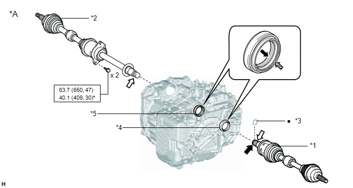
|
*A | for Gasoline Model |
- | - |
|
*1 | FRONT DRIVE SHAFT ASSEMBLY LH |
*2 | FRONT DRIVE SHAFT ASSEMBLY RH |
|
*3 | FRONT DRIVE SHAFT HOLE SNAP RING |
*4 | FRONT DRIVE SHAFT OIL SEAL LH |
|
*5 | FRONT DRIVE SHAFT OIL SEAL RH |
- | - |
 |
N*m (kgf*cm, ft.*lbf): Specified torque |
* | For use with SST |
|
â—Ź | Non-reusable part |
 |
MP grease |
 |
ATF WS |
 |
Toyota genuine oil seal side lip grease |
ILLUSTRATION
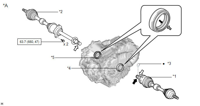
|
*A | for HV Model |
- | - |
|
*1 | FRONT DRIVE SHAFT ASSEMBLY LH |
*2 | FRONT DRIVE SHAFT ASSEMBLY RH |
|
*3 | FRONT DRIVE SHAFT HOLE SNAP RING |
*4 | FRONT DRIVE SHAFT OIL SEAL LH |
|
*5 | FRONT DRIVE SHAFT OIL SEAL RH |
- | - |
 |
N*m (kgf*cm, ft.*lbf): Specified torque |
â—Ź | Non-reusable part |
 |
MP grease |
 |
ATF WS |
 |
Toyota genuine oil seal side lip grease |
- | - |
ILLUSTRATION
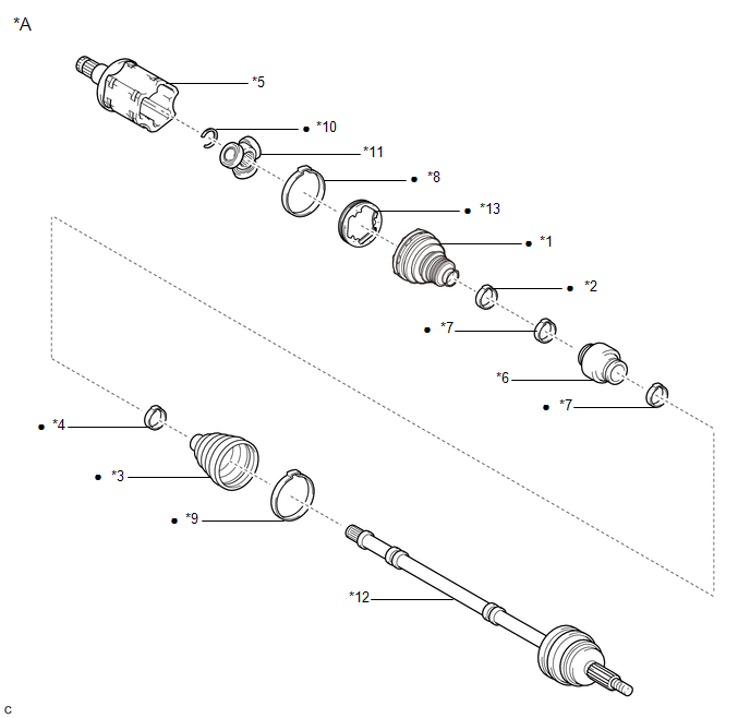
|
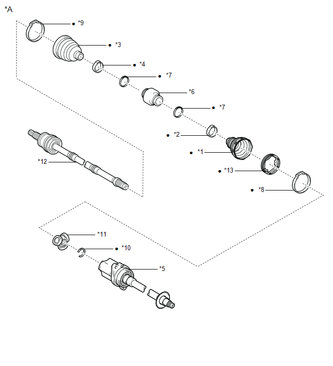
*A | for LH Side |
- | - |
|
*1 | FRONT AXLE INBOARD JOINT BOOT |
*2 | FRONT AXLE INBOARD JOINT BOOT CLAMP |
|
*3 | FRONT AXLE OUTBOARD JOINT BOOT |
*4 | FRONT AXLE OUTBOARD JOINT BOOT CLAMP |
|
*5 | FRONT DRIVE INBOARD JOINT ASSEMBLY |
*6 | FRONT DRIVE SHAFT DAMPER |
|
*7 | FRONT DRIVE SHAFT DAMPER CLAMP |
*8 | FRONT NO. 2 AXLE INBOARD JOINT BOOT CLAMP |
|
*9 | FRONT NO. 2 AXLE OUTBOARD JOINT BOOT CLAMP |
*10 | SHAFT SNAP RING |
|
*11 | TRIPOD JOINT |
*12 | FRONT DRIVE OUTBOARD JOINT SHAFT ASSEMBLY |
|
*13 | FRONT AXLE INBOARD JOINT GROMMET |
- | - |
|
â—Ź | Non-reusable part |
- | - |
ILLUSTRATION
|
*A | for RH Side |
- | - |
|
*1 | FRONT AXLE INBOARD JOINT BOOT |
*2 | FRONT AXLE INBOARD JOINT BOOT CLAMP |
|
*3 | FRONT AXLE OUTBOARD JOINT BOOT |
*4 | FRONT AXLE OUTBOARD JOINT BOOT CLAMP |
|
*5 | FRONT DRIVE INBOARD JOINT ASSEMBLY |
*6 | FRONT DRIVE SHAFT DAMPER |
|
*7 | FRONT DRIVE SHAFT DAMPER CLAMP |
*8 | FRONT NO. 2 AXLE INBOARD JOINT BOOT CLAMP |
|
*9 | FRONT NO. 2 AXLE OUTBOARD JOINT BOOT CLAMP |
*10 | SHAFT SNAP RING |
|
*11 | TRIPOD JOINT |
*12 | FRONT DRIVE OUTBOARD JOINT SHAFT ASSEMBLY |
|
*13 | FRONT AXLE INBOARD JOINT GROMMET |
- | - |
|
â—Ź | Non-reusable part |
- | - |
Disassembly
DISASSEMBLY
CAUTION / NOTICE / HINT
HINT:
- Use the same procedure for the RH side and LH side.
- The following procedure is for the LH side.
PROCEDURE
1. SEPARATE FRONT NO. 2 AXLE INBOARD JOINT BOOT CLAMP
(a) Secure the drive shaft in a vise between aluminum plates.
NOTICE:
Do not overtighten the vise.
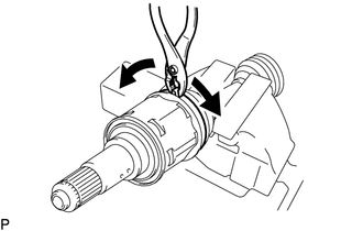
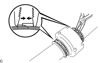
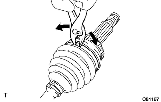
| (b) Using pliers, separate the front No. 2 axle inboard joint boot clamp as shown in the illustration. |
|
2. SEPARATE FRONT AXLE INBOARD JOINT BOOT CLAMP
HINT:
Perform the same procedure as for the front No. 2 axle inboard joint boot clamp.
3. SEPARATE FRONT AXLE INBOARD JOINT BOOT
(a) Separate the front axle inboard joint boot from the front drive inboard joint assembly.
4. REMOVE FRONT DRIVE INBOARD JOINT ASSEMBLY
(a) Remove the old grease from the front drive inboard joint assembly.
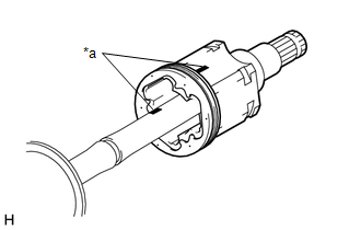
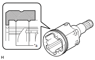
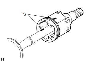
| (b) Put matchmarks on the front drive inboard joint assembly and front drive outboard joint shaft assembly.
NOTICE: Do not use a punch for the marks. | |
(c) Remove the front drive inboard joint assembly from the front drive outboard joint shaft assembly.
(d) Secure the drive shaft in a vise between aluminum plates.
NOTICE:
Do not overtighten the vise.
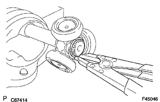
| (e) Using a snap ring expander, remove the shaft snap ring from the front drive outboard joint shaft assembly. |
|
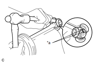
| (f) Put matchmarks on the front drive outboard joint shaft assembly and tripod joint.
NOTICE: Do not use a punch for the marks. | |
(g) Using a brass bar and a hammer, tap out the tripod joint from the front drive outboard joint shaft assembly.
NOTICE:
- Do not tap the rollers.
- Do not drop the tripod joint.
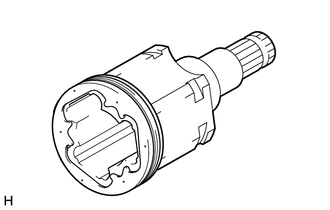
| (h) Remove the front axle inboard joint grommet from the front drive inboard joint assembly. |
|
5. REMOVE FRONT AXLE INBOARD JOINT BOOT
(a) Remove the front No. 2 axle inboard joint boot clamp, front axle inboard joint boot and front axle inboard joint boot clamp.
6. REMOVE FRONT DRIVE SHAFT DAMPER CLAMP (for LH Side)
| (a) Secure the drive shaft in a vise between aluminum plates.
NOTICE: Do not overtighten the vise. | |
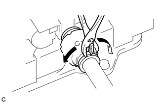
(b) Using pliers, separate the 2 front drive shaft damper clamps.
7. REMOVE FRONT DRIVE SHAFT DAMPER CLAMP (for RH Side)
(a) Secure the drive shaft in a vise between aluminum plates.
NOTICE:
Do not overtighten the vise.
| (b) Using needle-nose pliers, separate the 2 front drive shaft damper clamps. |
|
8. REMOVE FRONT DRIVE SHAFT DAMPER
(a)
Remove the front drive shaft damper and 2 front drive shaft damper
clamps from the front drive outboard joint shaft assembly.
9. SEPARATE FRONT NO. 2 AXLE OUTBOARD JOINT BOOT CLAMP
(a) Secure the drive shaft in a vise between aluminum plates.
NOTICE:
Do not overtighten the vise.
| (b) Using pliers, separate the front No. 2 axle outboard joint boot clamp. |
|
10. SEPARATE FRONT AXLE OUTBOARD JOINT BOOT CLAMP
HINT:
Perform the same procedure as for the front No. 2 axle outboard joint boot clamp.
11. REMOVE FRONT AXLE OUTBOARD JOINT BOOT
(a)
Remove the front axle outboard joint boot clamp, front axle outboard
joint boot and front No. 2 axle outboard joint boot clamp from the front
drive outboard joint shaft assembly.
(b) Remove the old grease from the outboard joint.
Inspection
INSPECTION
PROCEDURE
1. INSPECT FRONT DRIVE SHAFT ASSEMBLY
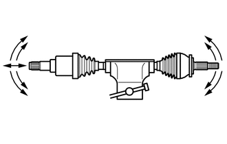
| (a) Check that there is no excessive play in the radial direction of the outboard joint. |
|
(b) Check that the inboard joint slides smoothly in the thrust direction.
(c) Check that there is no excessive play in the radial direction of the inboard joint.
(d) Check the boots for damage.
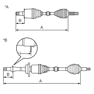
| (e) Check whether the drive shaft dimension (A) and (B) are within specification.
NOTICE: Keep the drive shaft assembly level during inspection.
Dimension (A) (for Gasoline Model): |
for LH Side | 598.75 mm (1.96 ft.) | |
for RH Side | 924.55 mm (3.03 ft.) |
Dimension (A) (for HV Model): |
for LH Side | 604.71 mm (1.98 ft.) | |
for RH Side | 905.65 mm (2.97 ft.) |
Dimension (B) (for Gasoline Model): |
for LH Side | 105.2 to 105.8 mm (4.15 to 4.16 in.) | |
for RH Side | 97.3 to 98.3 mm (3.84 to 3.87 in.) |
Dimension (B) (for HV Model): |
for LH Side | 86.8 to 87.6 mm (3.42 to 3.44 in.) | |
for RH Side | 83.7 to 84.7 mm (3.30 to 3.33 in.) | |
 |
|
*A | for LH Side | |
*B | for RH Side | | |
Installation
INSTALLATION
CAUTION / NOTICE / HINT
HINT:
- Use the same procedure for the RH side and LH side.
- The following procedure is for the LH side.
PROCEDURE
1. INSTALL FRONT DRIVE SHAFT HOLE SNAP RING
(a) Install a new front drive shaft hole snap ring.
NOTICE:
Face the end gap of the front drive shaft hole snap ring downward.
2. INSTALL FRONT DRIVE SHAFT ASSEMBLY LH
(a) Coat the snap ring of the front drive inboard joint assembly LH with MP grease.
(b) Coat the splines of the front drive inboard joint assembly LH with ATF WS.
(c)
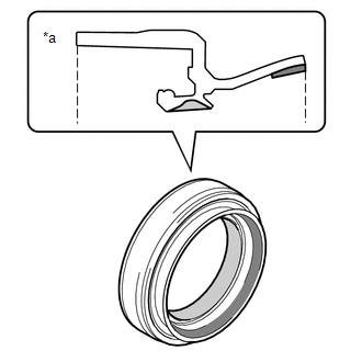
Coat the lip of the front drive shaft oil seal LH with MP grease and
Toyota genuine oil seal side lip grease as shown in the illustration.
|
*a | Cross Section of Front Drive Shaft Oil Seal LH |
 |
MP Grease |
 |
Toyota Genuine Oil Seal Side Lip Grease |
HINT:
Apply
a light coat of MP grease and Toyota genuine oil seal side lip grease
to the entire circumference of the front drive shaft oil seal LH.
| (d) Align the inboard joint splines, and using a brass bar and a hammer, install the front drive shaft assembly LH.
NOTICE:
- Face the end gap of the front drive shaft hole snap ring downward.
- Do not damage the front drive shaft oil seal LH.
- Do not damage the front axle inboard joint boot.
- Make sure to center the front drive shaft assembly LH during
installation to prevent damage to the front drive shaft hole snap ring.
HINT: Confirm whether the drive shaft is securely driven in by checking the reaction force and sound. |
|
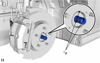
(e) Apply 0.1 to 0.3 g (0.00353 to 0.0105 oz) of Toyota Body Grease W to each of the 4 areas shown in the illustration.
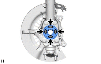
 |
Toyota Body Grease W |
| (f) Align the matchmarks and install the front drive shaft assembly LH to the front axle assembly.
NOTICE:
- Do not damage the front disc brake dust cover.
- Do not damage the front axle outboard joint boot.
- Check that there is no foreign matter on the deflector or contact surfaces.
- Do not push the front axle assembly towards the outside of the vehicle any further than necessary.
- Do not damage the deflector.
| |
3. INSTALL FRONT DRIVE SHAFT ASSEMBLY RH
(a) Coat the splines of the front drive inboard joint assembly RH with ATF WS.
(b)
Coat the lip of the front drive shaft oil seal RH with MP grease and
Toyota genuine oil seal side lip grease as shown in the illustration.
HINT:
Apply a light coat of Toyota genuine oil seal side lip grease to the entire circumference of the front drive shaft oil seal RH.
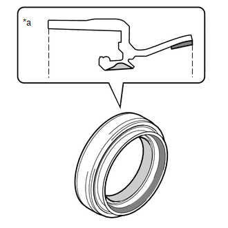
|
*a | Cross Section of Front Drive Shaft Oil Seal RH |
 |
MP Grease |
 |
Toyota Genuine Oil Seal Side Lip Grease |
(c) Align the inboard joint splines, and securely insert the front drive shaft assembly RH.
NOTICE:
- Do not damage the front drive shaft oil seal RH.
- Do not damage the front axle inboard joint boot.
(d) for Gasoline Model:
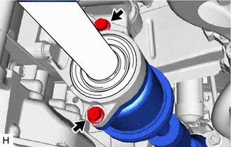
| (1) Install the front drive shaft assembly RH with the 2 bolts.
SST: 09961-00950 Torque: Specified tightening torque :
63.7 N·m {650 kgf·cm, 47 ft·lbf}
HINT:
|
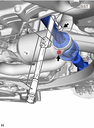 |
|
*a | Torque Wrench Fulcrum Length | | |
(e) for HV Model:
| (1) Install the front drive shaft assembly RH with the 2 bolts.
Torque: 63.7 N·m {650 kgf·cm, 47 ft·lbf} | |
(f) Apply 0.1 to 0.3 g (0.00353 to 0.0105 oz) of Toyota Body Grease W to each of the 4 areas shown in the illustration.
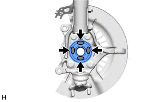
 |
Toyota Body Grease W |
| (g) Align the matchmarks and install the front drive shaft assembly RH to the front axle assembly.
NOTICE:
- Do not damage the front disc brake dust cover.
- Do not damage the front axle outboard joint boot.
- Check that there is no foreign matter on the deflector or contact surfaces.
- Do not push the front axle assembly towards the outside of the vehicle any further than necessary.
- Do not damage the deflector.
| |
4. CONNECT FRONT LOWER NO. 1 SUSPENSION ARM SUB-ASSEMBLY
Click here

5. INSTALL FRONT STABILIZER LINK ASSEMBLY
Click here 
6. CONNECT TIE ROD ASSEMBLY (for Gasoline Model)
Click here 
7. CONNECT TIE ROD ASSEMBLY (for HV Model)
Click here 
8. INSTALL FRONT SPEED SENSOR (w/o AVS)
Click here 
9. INSTALL FRONT SPEED SENSOR (w/ AVS)
Click here 
10. INSTALL FRONT AXLE SHAFT NUT
(a) Clean the threaded parts on the front drive shaft assembly and a new front axle shaft nut using non-residue solvent.
NOTICE:
- Make sure to perform this work even when using a new front drive shaft assembly.
- Keep the threaded parts free of oil and foreign matter.
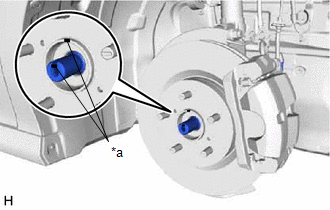
| (b) Using a 30 mm deep socket wrench, install the front axle shaft nut.
Torque: 294 N·m {2998 kgf·cm, 217 ft·lbf} HINT: Depress the brake pedal to prevent the drive shaft from rotating. |
|
(c) Using a chisel and hammer, stake the front axle shaft nut.
11. ADD AUTOMATIC TRANSAXLE FLUID (for Gasoline Model)
Click here 
12. ADD HYBRID TRANSAXLE FLUID (for HV Model)
Click here 
13. INSPECT HYBRID TRANSAXLE FLUID (for HV Model)
Click here 
14. INSPECT FOR HYBRID TRANSAXLE FLUID LEAK (for HV Model)
15. INSTALL FRONT WHEELS
Click here 
16. INSPECT AND ADJUST FRONT WHEEL ALIGNMENT
Click here

17. INSTALL FRONT FENDER APRON SEAL LH (for Gasoline Model)
Click here 
18. INSTALL FRONT FENDER APRON SEAL RH (for Gasoline Model)
Click here 
19. INSTALL REAR ENGINE UNDER COVER RH (for Gasoline Model)
Click here 
20. INSTALL REAR ENGINE UNDER COVER LH (for Gasoline Model)
Click here 
21. INSTALL NO. 1 ENGINE UNDER COVER (for Gasoline Model)
Click here 
22. INSTALL FRONT WHEEL OPENING EXTENSION PAD LH (for Gasoline Model)
Click here 
23. INSTALL FRONT WHEEL OPENING EXTENSION PAD RH (for Gasoline Model)
Click here 
24. INSTALL FRONT FENDER APRON SEAL LH (for HV Model)
Click here 
25. INSTALL FRONT FENDER APRON SEAL RH (for HV Model)
Click here 
26. INSTALL NO. 2 ENGINE UNDER COVER ASSEMBLY (for HV Model)
Click here 
27. INSTALL NO. 1 ENGINE UNDER COVER (for HV Model)
Click here 
28. INSTALL FRONT WHEEL OPENING EXTENSION PAD LH (for HV Model)
Click here 
29. INSTALL FRONT WHEEL OPENING EXTENSION PAD RH (for HV Model)
Click here 
30. CHECK FOR SPEED SENSOR SIGNAL (for Gasoline Model)
Click here 
31. CHECK FOR SPEED SENSOR SIGNAL (for HV Model)
Click here 
Reassembly
REASSEMBLY
CAUTION / NOTICE / HINT
HINT:
- Use the same procedure for the RH side and LH side.
- The following procedure is for the LH side.
PROCEDURE
1. INSTALL FRONT AXLE OUTBOARD JOINT BOOT
(a) Secure the drive shaft in a vise between aluminum plates.
NOTICE:
Do not overtighten the vise.
| (b)
Wrap the splines of the front drive outboard joint shaft assembly with
protective tape to prevent the boot from being damaged. | |
(c) Install new parts to the front drive outboard joint shaft assembly in the following order:
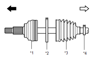
|
*1 | Front Drive Outboard Joint Shaft Assembly |
|
*2 | Front No. 2 Axle Outboard Joint Boot Clamp |
|
*3 | Front Axle Outboard Joint Boot |
|
*4 | Front Axle Outboard Joint Boot Clamp |
 |
Outboard Joint Side |
 |
Inboard Joint Side |
(1) Front No. 2 axle outboard joint boot clamp
(2) Front axle outboard joint boot
(3) Front axle outboard joint boot clamp
(d) Pack the joint portion of the front drive outboard joint shaft assembly and front axle outboard joint boot with grease.
Standard Grease Capacity (for Gasoline Model):
86 g (3.03 oz)
Standard Grease Capacity (for HV Model):
110 g (3.88 oz)
(e) Install the front axle outboard joint boot to the front drive outboard joint shaft assembly groove.
NOTICE:
- Do not allow grease to adhere to the boot clamp track of the outboard joint boot.
- Keep the inside of the outboard joint boot free of foreign matter.
2. INSTALL FRONT AXLE OUTBOARD JOINT BOOT CLAMP
(a) Secure the drive shaft in a vise between aluminum plates.
NOTICE:
Do not overtighten the vise.
(b) Install the front axle outboard joint boot clamp to the front axle outboard joint boot.
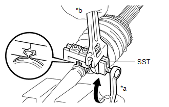
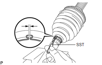
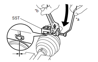
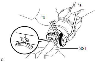
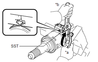
| (c) Place SST to the front axle outboard joint boot clamp, press it against the boot and slightly tighten SST.
SST: 09521-24010 | |
(d) Tighten SST so that the front axle outboard joint boot clamp is pinched.
NOTICE:
Do not overtighten SST.
(e) Remove SST.
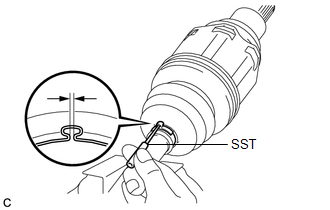
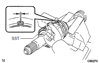
| (f) Using SST, measure the clearance of the front axle outboard joint boot clamp.
SST: 09240-00021 Clearance: 0.5 to 1.5 mm (0.0197 to 0.0590 in.)
If the clearance is not as specified, retighten SST. | |
3. INSTALL FRONT NO. 2 AXLE OUTBOARD JOINT BOOT CLAMP
(a) Secure the drive shaft in a vise between aluminum plates.
NOTICE:
Do not overtighten the vise.
(b) Install the front No. 2 axle outboard joint boot clamp to the front axle outboard joint boot.
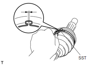
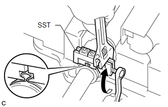
| (c) Place SST onto the front No. 2 axle outboard joint boot clamp, press it against the boot and slightly tighten SST.
SST: 09521-24010 | |
(d) Tighten SST so that the front No. 2 axle outboard joint boot clamp is pinched.
NOTICE:
Do not overtighten SST.
(e) Remove SST.
| (f) Using SST, measure the clearance of the front No. 2 axle outboard joint boot clamp.
SST: 09240-00021 Clearance: 0.5 to 1.5 mm (0.0197 to 0.0590 in.)
If the clearance is not as specified, retighten SST. | |
4. INSTALL FRONT DRIVE SHAFT DAMPER
| (a)
Temporarily install the front drive shaft damper and 2 new front drive
shaft damper clamps to the front drive outboard joint shaft assembly as
shown in the illustration. |
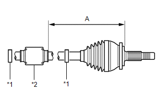 |
|
*1 | Front Drive Shaft Damper Clamp | |
*2 | Front Drive Shaft Damper | | |
(b) Set the dimension (A) as specified below.
Dimension (A) (for Gasoline Model):
226.9 to 230.9 mm (8.94 to 9.09 in.)
Dimension (A) (for HV Model):
223.4 to 227.4 mm (8.80 to 8.95 in.)
5. INSTALL FRONT DRIVE SHAFT DAMPER CLAMP (for LH Side)
(a) Secure the drive shaft in a vise between aluminum plates.
NOTICE:
Do not overtighten the vise.
(b) Install the 2 front drive shaft damper clamps to the front drive shaft damper.
NOTICE:
Make sure to install the clamps in the correct position.
| (c) Place SST onto the front drive shaft damper clamp, press it against the damper and slightly tighten SST.
SST: 09521-24010 | |
(d) Tighten SST so that the front drive shaft damper clamp is pinched.
NOTICE:
Do not overtighten SST.
(e) Remove SST.
| (f) Using SST, measure the clearance of the front drive shaft damper clamp.
SST: 09240-00021 Clearance: 0.5 to 1.5 mm (0.0197 to 0.0590 in.)
If the clearance is not as specified, retighten SST. | |
6. INSTALL FRONT DRIVE SHAFT DAMPER CLAMP (for RH Side)
(a) Secure the drive shaft in a vise between aluminum plates.
NOTICE:
Do not overtighten the vise.
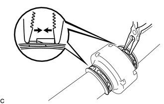
| (b) Using needle-nose pliers, install the 2 front drive shaft damper clamps as shown in the illustration.
NOTICE:
- Be sure to install the clamps in the correct position.
- Do not damage the front drive shaft damper.
| |
7. INSTALL FRONT DRIVE INBOARD JOINT ASSEMBLY
(a) Install new parts to the front drive outboard joint shaft assembly in the following order:
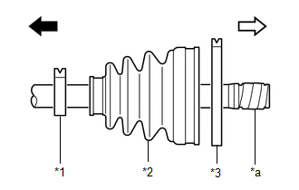
|
*1 | Front Axle Inboard Joint Boot Clamp |
|
*2 | Front Axle Inboard Joint Boot |
|
*3 | Front No. 2 Axle Inboard Joint Boot Clamp |
|
*a | Protective Tape |
 |
Outboard Joint Side |
 |
Inboard Joint Side |
(1) Front axle inboard joint boot clamp
(2) Front axle inboard joint boot
(3) Front No. 2 axle inboard joint boot clamp
(b) Secure the drive shaft in a vise between aluminum plates.
NOTICE:
Do not overtighten the vise.
(c) Remove the protective tape.
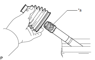
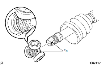
| (d) Align the matchmarks and install the tripod joint to the front drive outboard joint shaft assembly.
NOTICE: Face the serrated side of the tripod joint outward and install it to the outboard joint end. |
|
(e) Using a brass bar and a hammer, install the tripod joint to the front drive outboard joint shaft assembly.
NOTICE:
- Do not tap the rollers.
- Keep the tripod joint free of foreign matter.
- Be sure to install the tripod joint in the correct direction.
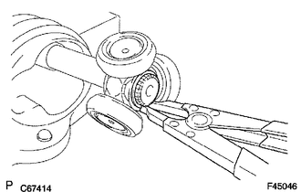
| (f) Using a snap ring expander, install a new shaft snap ring to the front drive outboard joint shaft assembly. |
|
(g) Pack the front drive inboard joint assembly and front axle inboard joint boot with grease.
Standard Grease Capacity:
195 g (6.88 oz)
| (h) Install a new front axle inboard joint grommet to the front drive inboard joint assembly.
NOTICE:
- Securely fit the protrusion on the front axle inboard joint grommet into the front drive inboard joint assembly.
- Make sure that the lip of the front axle inboard joint grommet is not damaged.
| |
| (i) Align the matchmarks and install the front drive inboard joint assembly to the front drive outboard joint shaft assembly. |
|
8. INSTALL FRONT AXLE INBOARD JOINT BOOT
(a) Install the front axle inboard joint boot to the front drive inboard joint assembly.
| (b) Check whether the dimension (A) of each drive shaft is within the specification.
NOTICE: Keep the drive shaft assembly level during inspection.
Dimension (A) (for Gasoline Model): |
for LH Side | 598.75 mm (1.96 ft.) | |
for RH Side | 924.55 mm (3.03 ft.) |
Dimension (A) (for HV Model): |
for LH Side | 604.71 mm (1.98 ft.) | |
for RH Side | 905.65 mm (2.97 ft.) | |
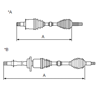 |
|
*A | for LH Side | |
*B | for RH Side | | |
9. INSTALL FRONT AXLE INBOARD JOINT BOOT CLAMP
(a) Secure the drive shaft in a vise between aluminum plates.
NOTICE:
Do not overtighten the vise.
(b) Install the front axle inboard joint boot clamp to the front axle inboard joint boot.
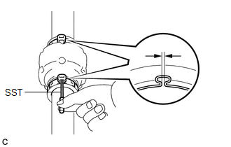
| (c) Place SST onto the front axle inboard joint boot clamp, press it against the boot and slightly tighten SST.
SST: 09521-24010 | |
(d) Tighten SST so that the front axle inboard joint boot clamp is pinched.
NOTICE:
Do not overtighten SST.
(e) Remove SST.
| (f) Using SST, measure the clearance of the front axle inboard joint boot clamp.
SST: 09240-00021 Clearance: 0.5 to 1.5 mm (0.0197 to 0.0590 in.)
If the clearance is not as specified, retighten SST. | |
10. INSTALL FRONT NO. 2 AXLE INBOARD JOINT BOOT CLAMP
(a) Secure the drive shaft in a vise between aluminum plates.
NOTICE:
Do not overtighten the vise.
(b) Install the front No. 2 axle inboard joint boot clamp to the front axle inboard joint boot.
| (c) Place SST onto the front No. 2 axle inboard joint boot clamp, press it against the boot and slightly tighten SST.
SST: 09521-24010 | |
(d) Tighten SST so that the front No. 2 axle inboard joint boot clamp is pinched.
NOTICE:
Do not overtighten SST.
(e) Remove SST.
| (f) Using SST, measure the clearance of the front No. 2 axle inboard joint boot clamp.
SST: 09240-00021 Clearance: 0.5 to 1.5 mm (0.0197 to 0.0590 in.)
If the clearance is not as specified, retighten SST. | |
11. INSPECT FRONT DRIVE SHAFT ASSEMBLY
Click here

Removal
REMOVAL
CAUTION / NOTICE / HINT
The
necessary procedures (adjustment, calibration, initialization, or
registration) that must be performed after parts are removed and
installed, or replaced during front drive shaft assembly
removal/installation are shown below.
Necessary Procedures After Parts Removed/Installed/Replaced |
Replaced Part or Performed Procedure |
Necessary Procedure | Effect/Inoperative Function when Necessary Procedure not Performed |
Link |
|
*1: for Gasoline Model
|
| Front wheel alignment adjustment |
- Clear zero point calibration data.
- Perform yaw rate and acceleration sensor zero point calibration.
|
- DTCs are stored
- ABS warning light illuminates
- Brake warning light / yellow (minor malfunction) illuminates
- Slip indicator light illuminates
- VSC disabled or malfunctions
| for HV Model:
 for Gasoline Model:
 |
|
Replacement of automatic transaxle fluid*1 |
ATF thermal degradation estimate reset |
The value of the Data List item "ATF Thermal Degradation Estimate" is not estimated correctly |
 |
HINT:
- Use the same procedure for the RH side and LH side.
- The following procedure is for the LH side.
PROCEDURE
1. REMOVE FRONT WHEELS
Click here

2. REMOVE FRONT WHEEL OPENING EXTENSION PAD LH (for Gasoline Model)
Click here 
3. REMOVE FRONT WHEEL OPENING EXTENSION PAD RH (for Gasoline Model)
Click here 
4. REMOVE NO. 1 ENGINE UNDER COVER (for Gasoline Model)
Click here 
5. REMOVE REAR ENGINE UNDER COVER LH (for Gasoline Model)
Click here 
6. REMOVE REAR ENGINE UNDER COVER RH (for Gasoline Model)
Click here 
7. REMOVE FRONT FENDER APRON SEAL LH (for Gasoline Model)
Click here 
8. REMOVE FRONT FENDER APRON SEAL RH (for Gasoline Model)
Click here 
9. REMOVE FRONT WHEEL OPENING EXTENSION PAD LH (for HV Model)
Click here 
10. REMOVE FRONT WHEEL OPENING EXTENSION PAD RH (for HV Model)
Click here 
11. REMOVE NO. 1 ENGINE UNDER COVER (for HV Model)
Click here 
12. REMOVE NO. 2 ENGINE UNDER COVER ASSEMBLY (for HV Model)
Click here 
13. REMOVE FRONT FENDER APRON SEAL LH (for HV Model)
Click here 
14. REMOVE FRONT FENDER APRON SEAL RH (for HV Model)
Click here 
15. DRAIN AUTOMATIC TRANSAXLE FLUID (for Gasoline Model)
Click here 
16. DRAIN HYBRID TRANSAXLE FLUID (for HV Model)
Click here 
17. REMOVE FRONT AXLE SHAFT NUT
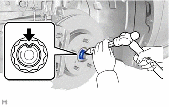
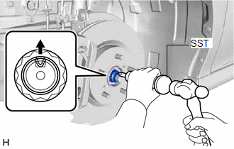
| (a) Using SST and a hammer, release the staked part of the front axle shaft nut.
SST: 09930-00010 NOTICE: Fully loosen the staked part of the front axle shaft nut, otherwise the threads of the drive shaft may be damaged. |
|
(b) While applying the brakes, remove the front axle shaft nut.
18. SEPARATE FRONT SPEED SENSOR (w/o AVS)
Click here 
19. SEPARATE FRONT SPEED SENSOR (w/ AVS)
Click here 
20. SEPARATE TIE ROD ASSEMBLY (for Gasoline Model)
Click here 
21. SEPARATE TIE ROD ASSEMBLY (for HV Model)
Click here 
22. SEPARATE FRONT STABILIZER LINK ASSEMBLY
Click here 
23. SEPARATE FRONT LOWER NO. 1 SUSPENSION ARM SUB-ASSEMBLY
Click here 
24. SEPARATE FRONT DRIVE SHAFT ASSEMBLY
Click here 
25. REMOVE FRONT DRIVE SHAFT ASSEMBLY LH
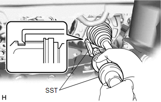
| (a) Using SST, remove the front drive shaft assembly LH. SST: 09520-01010
SST: 09520-24010 09520-32040
NOTICE:
- Do not damage the front drive shaft oil seal LH.
- Do not damage the front axle inboard joint boot.
- Do not drop the front drive shaft assembly LH.
| |
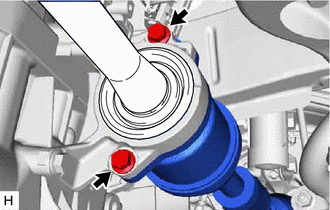
26. REMOVE FRONT DRIVE SHAFT ASSEMBLY RH
| (a) Remove the 2 bolts and pull out the drive shaft together with the drive shaft bearing case sub-assembly. |
|
(b) Remove the front drive shaft assembly RH from the drive shaft bearing bracket.
NOTICE:
- Do not damage the front drive shaft oil seal RH.
- Do not damage the front axle inboard joint boot.
- Do not drop the front drive shaft assembly RH.
HINT:
If it is
difficult to disengage the fitting, tap the end of the front drive
inboard joint assembly with a brass bar and a hammer.
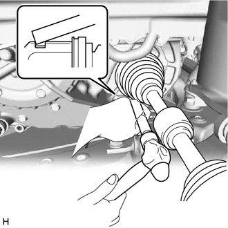
27. REMOVE FRONT DRIVE SHAFT HOLE SNAP RING
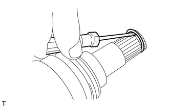
| (a) Using a screwdriver, remove the front drive shaft hole snap ring. |
|


